SM482PLUS_Admin(Eng_Ver2.8).pdf - 第491页
15-37 System Setup 15.5. Pref. [F10] Sets various options needed fo r equipment operation. When th is button is clicked on, the following dialog bo x is displayed. 15.5.1. <General > tab dialog Sets general items r…
15-36
Multi-Functional Placer SM482(L) PLUS Administrator’s Guide
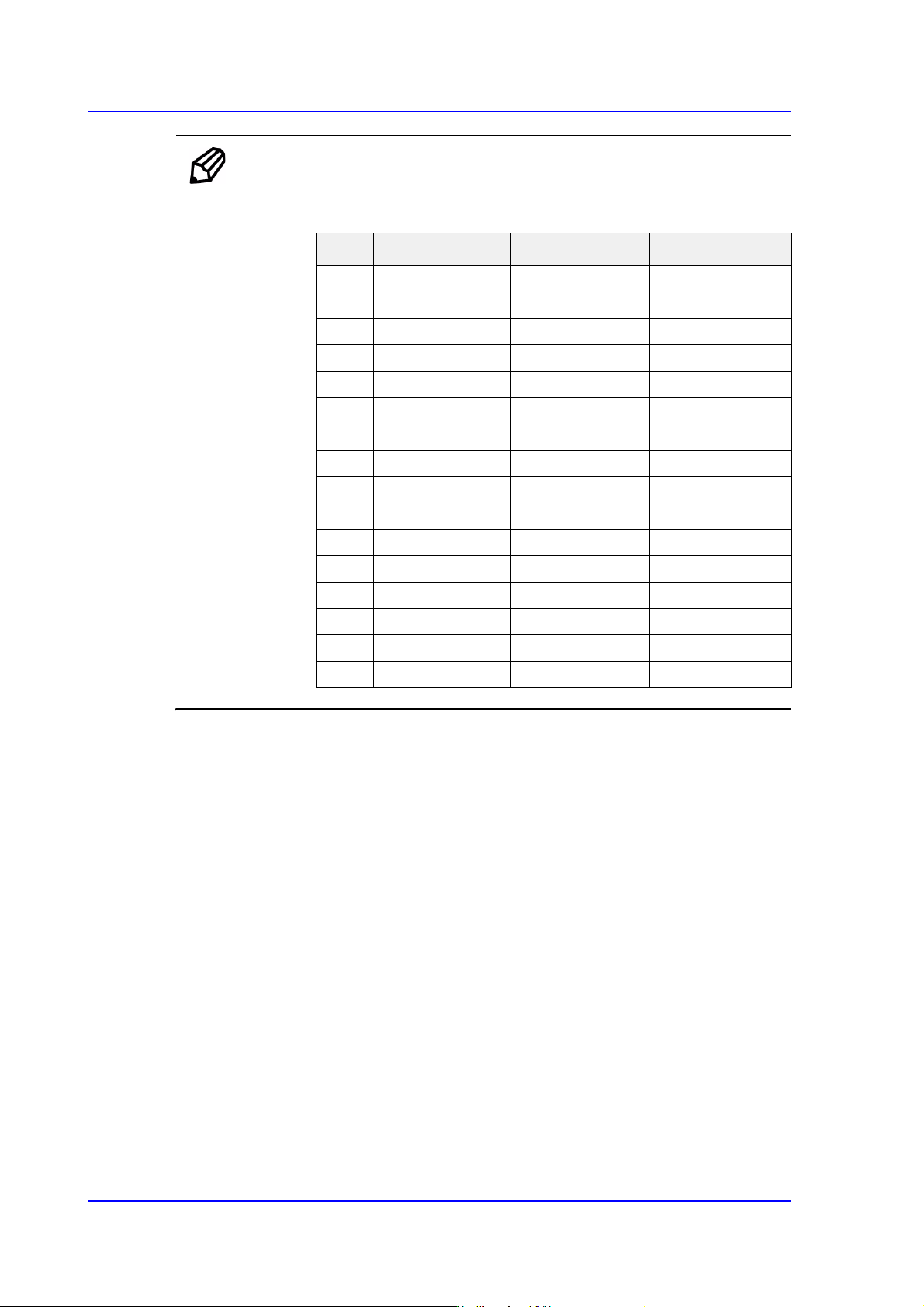
Ref. The test result value must be within ±10 from the following reference
value.
Side Outer Coaxial
00 0 0
112 20 17
224 35 31
340 50 45
458 65 60
576 80 74
694 100 94
7 110 120 113
8 122 140 133
9 134 170 140
10 146 190 140
11 158 200 140
12 168 210 140
13 178 220 140
14 188 240 140
15 188 254 140
15-37
System Setup
15.5. Pref. [F10]
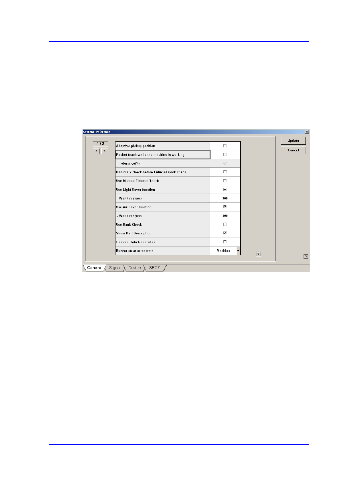
Sets various options needed for equipment operation. When this button is clicked on, the
following dialog box is displayed.
15.5.1. <General> tab dialog
Sets general items related to the equipment operation.
Figure15.16 “General” tab dialog
<Adaptive pickup position> check box
If this check box is selected, when the equipment stops due to pickup error, the
coordinate calibrated to the pickup point of the corresponding feeder is reflected when
restarting the work.
The offset between the center of the part recognized through the vision system and the
center of the head that performed pickup is reflected automatically.
If this check box is selected, the edit box of the selected items is enabled right below it.
This edit box is used to adjust the tolerance when performing synchronized pickup.
At this time, the tolerance for the synchronized pickup is as follows:
Tolerance for synchronized pickup =Sync Pickup Tol +[Sync Pickup Tol X (a /100 )]
Sync Pickup Tolerance is that of the common data for the corresponding part.
'a' is the value entered into the edit box.

15-38
Multi-Functional Placer SM482(L) PLUS Administrator’s Guide
Memo For parts fed by an 8mm tape feeder, it is recommended that this
function be applied.
For parts fed by a tape feeder with tape larger than 8mm, if this
function is applied, the part dumping rate can be reduced. However,
do not use this function for parts with the following characteristics.
When a part moves significantly in the tape pocket.
When it is difficult to set the part pickup height accurately.
(Example: Same types of parts with a great variation in
thickness.)
<Pocket teach while the machine is working> check box
If this check box is selected, the Pocket Teach function is applied when picking up the
part supplied through the supplying device that was set to use the Pocket Teach in the
'Feeders' dialog box.
If this check box is selected, the edit box of the selected items is enabled right below it.
This edit box is used to adjust the tolerance when performing synchronized pickup.
At this time, the tolerance for the synchronized pickup is as follows:
Tolerance for synchronized pickup =Sync Pickup Tol +[Sync Pickup Tol X (a /100 )]
Sync Pickup Tolerance is that of the common data for the corresponding part.
'a' is the value entered into the edit box.
If the Sync Pickup Tolerance of the corresponding part is 15, and the value of 'a' is
67, the Sync Pickup Tolerance becomes 25.05%.
Sync Pickup Tolerance =15 +[15 X (67 /100 )] =25.05 %
<Bad mark check before Fiducial mark check> check box
If this button is checked, executes bad mark check before fiducial mark check when
the PCB is loaded.
Recognizes the bad mark in multi array PCB first, and makes skip checking the
fiducial mark of the PCB that does not need to be installed.
However, when the PCB is fixed on the placement position of the conveyor, and setup
position of the bad mark changes due to PCB shape causing confirmation of bad mark
to be done first, then errors can occur as the position of the setup does not match.
In this case, the fiducial mark must be recognized first, and the position of the bad
mark must be compensated accurately.
<Use Manual Fiducial Teach> check box
When placing the parts on the PCB in the Product menu, if the fiducial mark has been
recognized incorrectly, this function is used to solve the problem by displaying the