SM482PLUS_Admin(Eng_Ver2.8).pdf - 第447页
14-75 Machine Calibration Memo The reference values for the calibratio n of the Fly t o Fix Offset is as follows. Offset X : -0.0 50 ~ 0.050(mm) Offset Y : -0.050 ~ 0.050(m m) The reference values for the calibra tio…
14-74
Multi-Functional Placer SM482(L) PLUS Administrator’s Guide
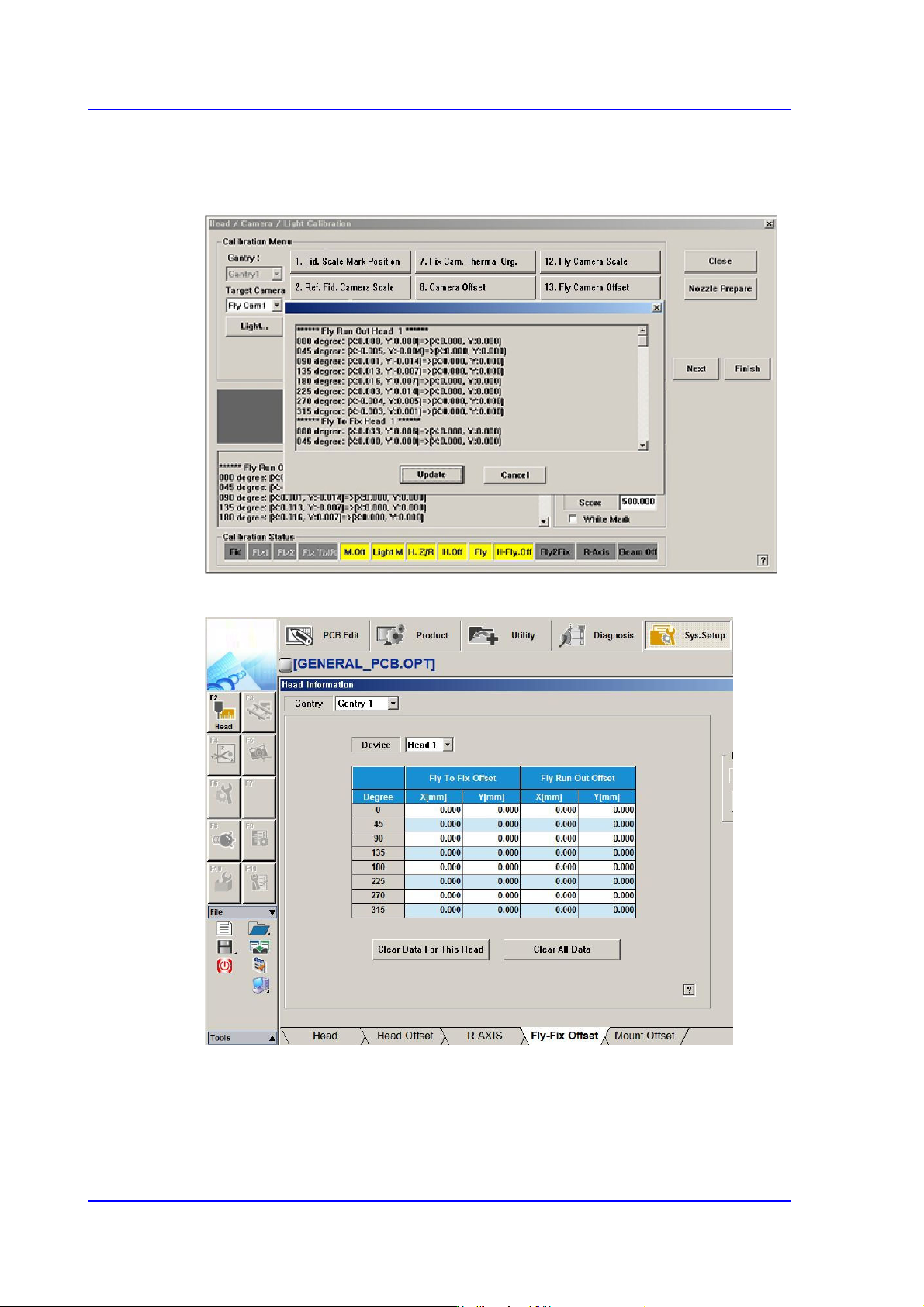
10. If the calibration procedure is completed for all heads normally, the result is displayed
as shown in the following figure. Click the <Update> button to apply the calibration
value.
11. The measurement result can be confirmed in the Fly-Fix Offset dialogbox.

14-75
Machine Calibration
Memo The reference values for the calibration of the Fly to Fix Offset is as
follows.
Offset X : -0.050 ~ 0.050(mm)
Offset Y : -0.050 ~ 0.050(mm)
The reference values for the calibration of the Fly Runout Offset is as
follows.
Offset X : -0.020 ~ 0.020(mm)
Offset Y : -0.020 ~ 0.020(mm)
14.3.7.10. R-Axis Offset Calibration
If the recognized angle and placement angle of the R axis are different, the R axis error
cannot be compensated through the Vision. Therefore, the placement accuracy decreases.
Therefore, perform R axis offset calibration to minimize such error by compensating an
approximate value with the R axis motion data.
The CNT20 nozzle must be used to perform this calibration.
The following is the procedure to calibrate the ‘R-Axis Offset’:
1. Click the <Nozzle Prepare> button and insert the CNT20 nozzle into the No. 1 hole of
the ANC manually.
2. If the <15. R-Axis Offset> is clicked after selecting the <Automatic Next> check box,
calibration is performed for the selected gantry automatically.
If calibration is performed after selecting the <No Real Motion [Manual]> check box,
the nozzle is inserted into each head manually. Click the <Next> button to move onto
the next step.
If calibration is performed without selecting either the <Automatic> check box or
<Manual> check box, the nozzle is changed automatically for the currently selected
nozzle. Click the <Next> button to move onto the next step.
If the <15. R-Axis Offset> button is selected, the message “First, We must Put all
Nozzles From Heads on Manually. To Move down Z Axis, Click [Next]” appears.
Click the <Next> button to move down the Z axis of the head in order to manually
move all nozzles inserted in the nozzle-holder of the head.
14-76
Multi-Functional Placer SM482(L) PLUS Administrator’s Guide
3. Then, after the head assembly moves to the home position on the machine, move all Z
axes down. At this time, remove all inserted nozzles manually.
4. Then the message “Next Attach the Calibration Tool to Head 1. Click [Next] for
Moving Down Head. After Moving, Attach the Tool to Head Manually” appears.
Click the <Next> button after inserting the CNT20 nozzle in the nozzle-holder of
Head #1 manually.
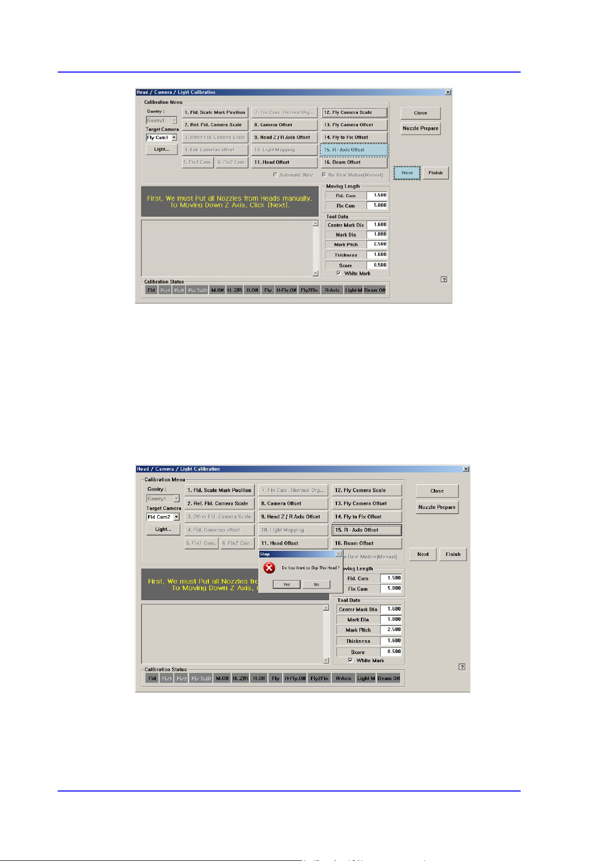
5. The message “Z Axis moving down…. Please Wait for a Moment.” appears, and the
dialog box asking whether to skip the calibration of Head1 is displayed. Click “Yes” to
skip or click “No” to proceed with the calibration. And then click the <Next> button.
6. The message “Move To Center Position of Calibration Tool. To Move, Click [Next].”
appears. appears in the message window. Click the <Next> button to move the head
assembly to the calibration tool position on the ANC.
7. The message “Calibration is Prepared. To Calibrate, Click [Next]” appears. At this