SM482PLUS_Admin(Eng_Ver2.8).pdf - 第389页
14-17 Machine Calibration Z-axis Height T eaching (Hea d Z T eaching) The default value is 50. 5. 1) Select the Curr ent Position( ) in the V iew menu and ex ecute the “Position” dialog box. 2) Click the <Manual T o…
14-16
Multi-Functional Placer SM482(L) PLUS Administrator’s Guide
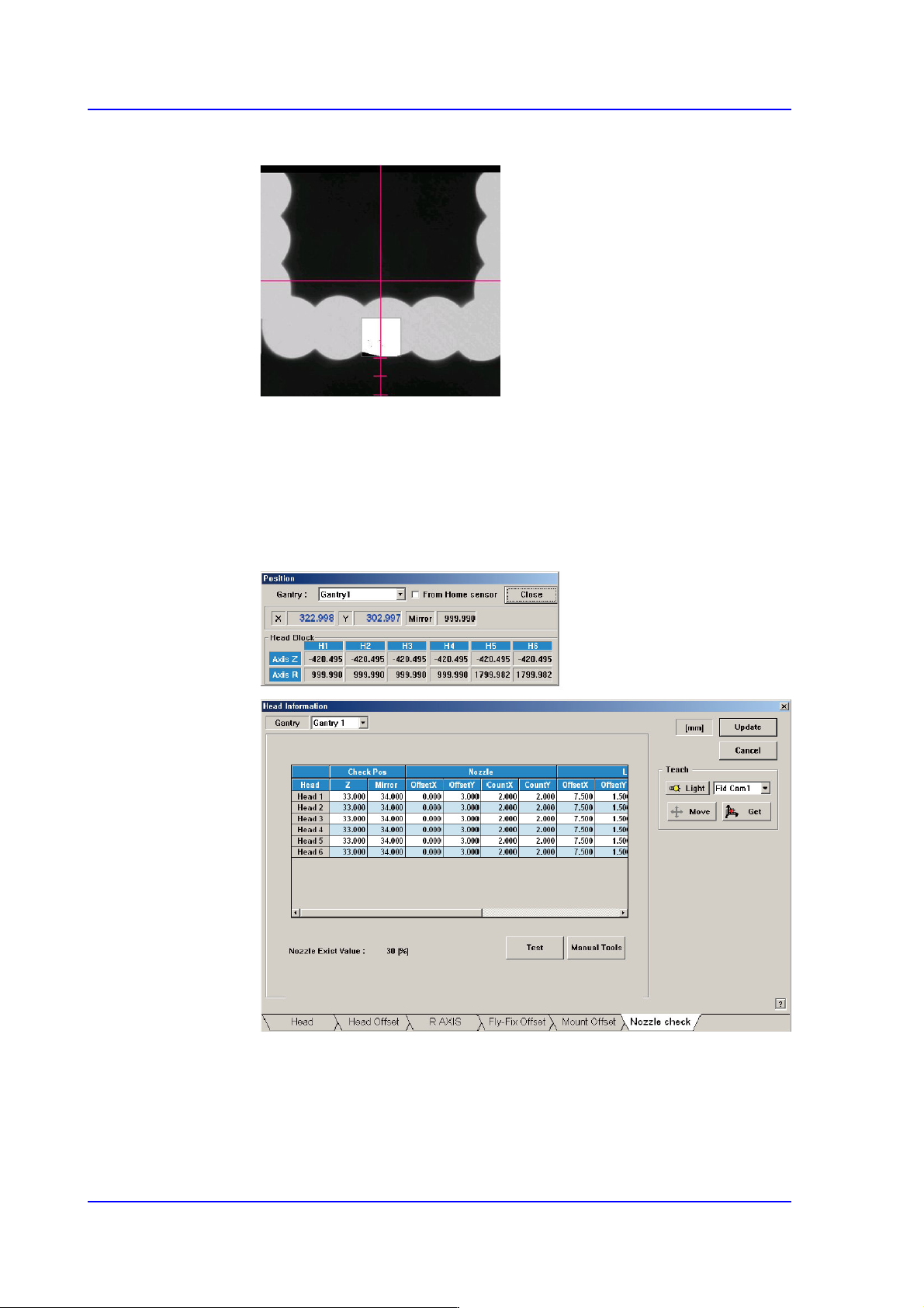
<When using the FOV 16mm Fly Camera>
In the case of the fly-camera with FOV 16mm, match the bottom of the LED
with the second scale from the bottom of the cross hair in the ‘SMVision’
window.
6) Close the Manual Tools dialog box..
7) At this time, apply the Mirror value in the “Position” dialog box as the Mirror
value of the Check Position.
14-17
Machine Calibration
Z-axis Height Teaching (Head Z Teaching)
The default value is 50.5.
1) Select the Current Position( ) in the View menu and execute the
“Position” dialog box.
2) Click the <Manual Tools> button in the ‘Nozzle Check’ tab dialog box to
execute the ‘Manual Control’ dialog box.
3) Select the Z in the <Axis> combo box of the Axis Tab dialog box.
4) In the ‘Camera’ dialog box, select the camera corresponding to the head that
will check the existance of the nozzle.
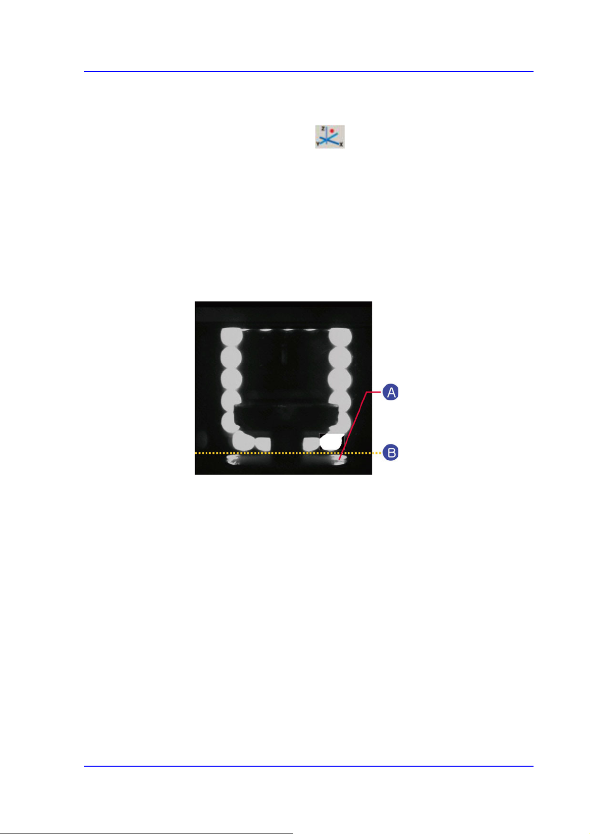
5) Move the Z-axis so that the nozzle wing surface contacts the bottom of the
outer lighting device.
A: Nozzle wing
B: Outer Lighting Device Bottom
6) Close the Manual Tools dialog box.
14-18
Multi-Functional Placer SM482(L) PLUS Administrator’s Guide
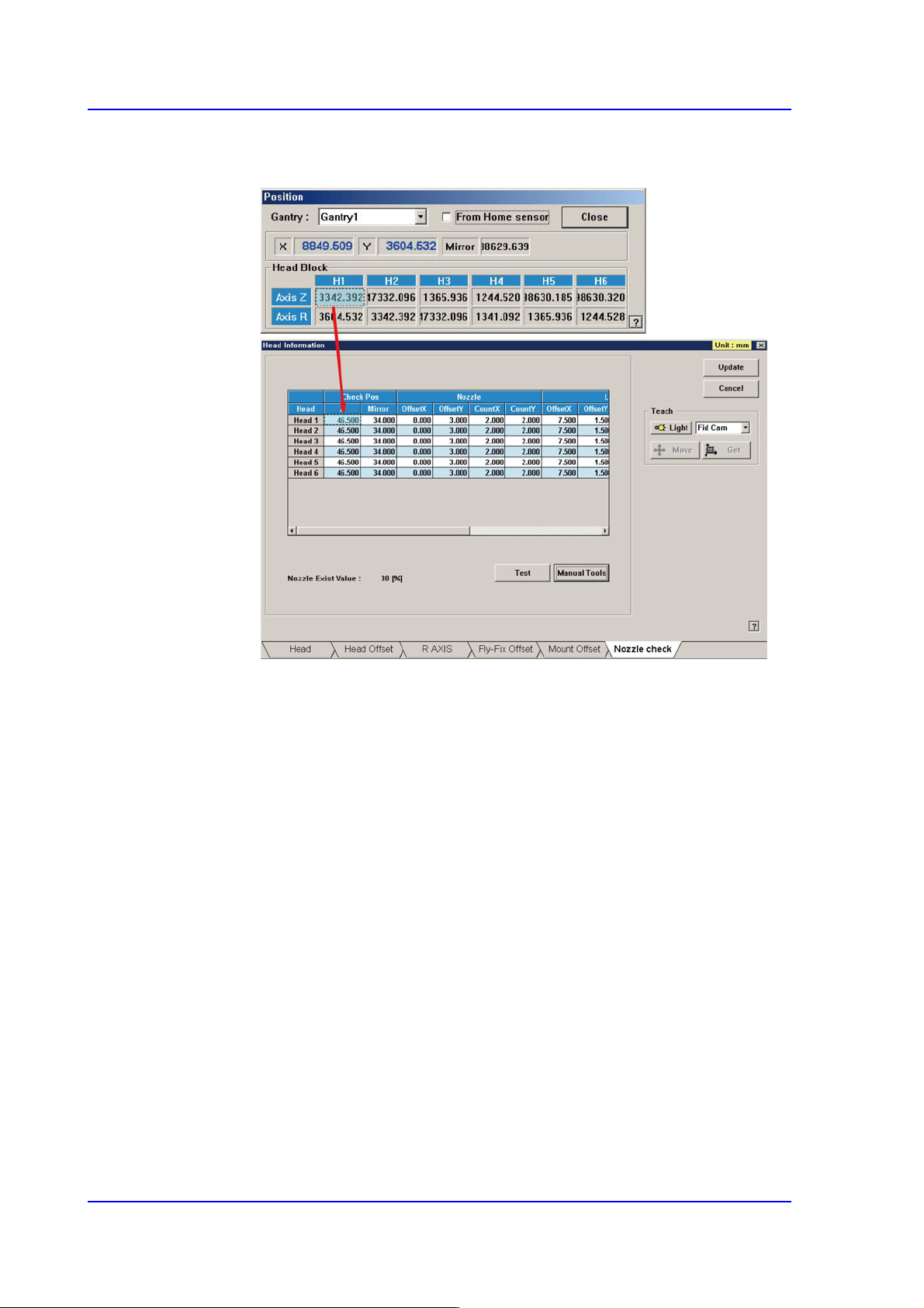
7) At this time, apply the Axis Z value in the “Position” dialog box as the Z value
of the Check Position.
Nozzle Offset Teaching
1) If the Offset X and Y cells are clicked, the <Test> button is activated. At this
time click the <Test> button
2) The area to be tested is displayed in the box shape of the ‘SMVision’ window.
Set the value of OffsetX and OffsetY so that the test box comes to the center
of the bottom of the LED. The coordinate system used to set the X and Y
values is the Right-Down coordinate system.