SM482PLUS_Admin(Eng_Ver2.8).pdf - 第330页
12-4 Multi-Functional Placer SM48 2(L) Administrator’s Guide <Detail> button Executes the following dialog box used to se t the details for the “Use LED flip auto check”. This button is enable d only when the <…
12-3
LED placement
12.2. LED part registration
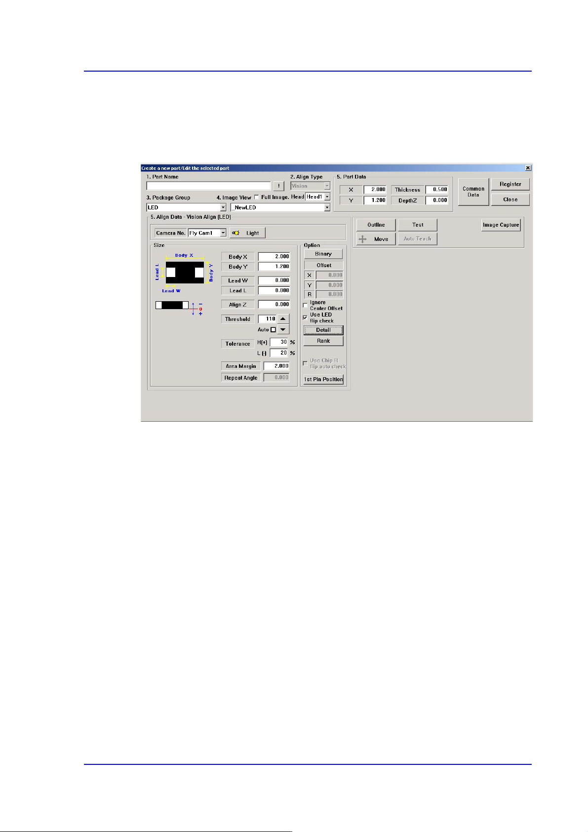
When registering an LED part, click the <New Part> button in the “Register Part” dialog
box to execute the “Create New Part/ Edit Selected Part” dialog box.
Figure12.1 “Create a new part/Edit the selected part” dialog box
Major options for LED part recognition are as follows:
<Use LED flip check> check box
This is selected to use the function that checks the turnover of the LED. This is applied
only to Chip-R, Chip-C, Chip-circle, Chip-tantal, Chip-aluminum, Melf, LED, etc.
For more details, refer the “<Detail> button”.
12-4
Multi-Functional Placer SM482(L) Administrator’s Guide
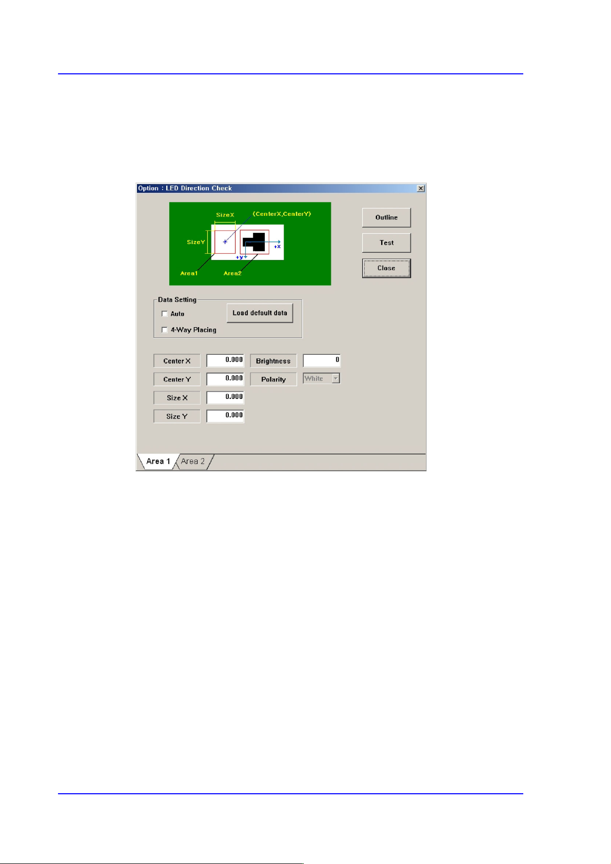
<Detail> button
Executes the following dialog box used to set the details for the “Use LED flip auto
check”. This button is enabled only when the <Use LED flip auto check> check box is
selected.
Figure12.2 “LED direction check” check box
Set the White area of the LED in the ‘Area 1’ tab dialog box.
Center X
Refers to the coordinate in the X direction of the White area based on the part
center. (Refers to the figure in the dialog box)
Center Y
Refers to the coordinate in the Y direction of the White area based on the part
center. (Refers to the figure in the dialog box)
Size X
Size of the tetragonal area in the X direction (mm)
Size Y
Size of the tetragonal area in the Y direction (mm)
Brightness
Refers to the reference value of the White area. The White area with a value
less than the reference value can be considered normal. Generally, it has a
value of 200 and above.
12-5
LED placement
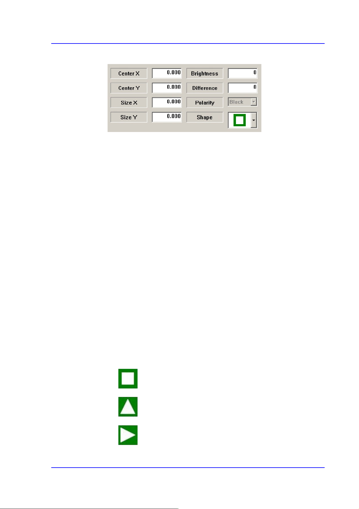
Set the Black area of the LED in the ‘Area 2’ tab dialog box.
Center X
Refers to the coordinate in the X direction of the Black area based on the part
center. (Refers to the figure in the dialog box)
Center Y
Refers to the coordinate in the Y direction of the Black area based on the part
center. (Refers to the figure in the dialog box)
Size X
Size of the tetragonal area in the X direction (mm)
Size Y
Size of the tetragonal area in the Y direction (mm)
Brightness
Refers to the reference value of the White area. The White area with a value
greater than the reference value can be considered normal.
Difference
Input the minimum difference in the brightness between <Area 1> and <Area
2>. Generally, input 40.
Shape
Select a shape according to the mark or concavo-convex on the bottom surface of
the LED. If the concavo-convex shape is selected, the brightness of the selected
area as well as the direction of a protrusion are checked. This, therefore, prevents
the part from being placed upside down.
: There is no shape.
: Triangle mark in the 0° direction.
: Triangle mark in the 90° direction.