SM482PLUS_Admin(Eng_Ver2.8).pdf - 第43页
xxix Mouse manipulation The following terms are relate d to manipulating the mouse. Click or select Press once the corresponding item with the left Button of the mouse by moving the pointer of the mouse. Double cli…
Multi-Functional Placer SM482(L) PLUS Administrator’s Guide
xxviii
Group
The above items are gathered into this area. In this manual, it is called “<XX>
group” based on the name XX above the group.
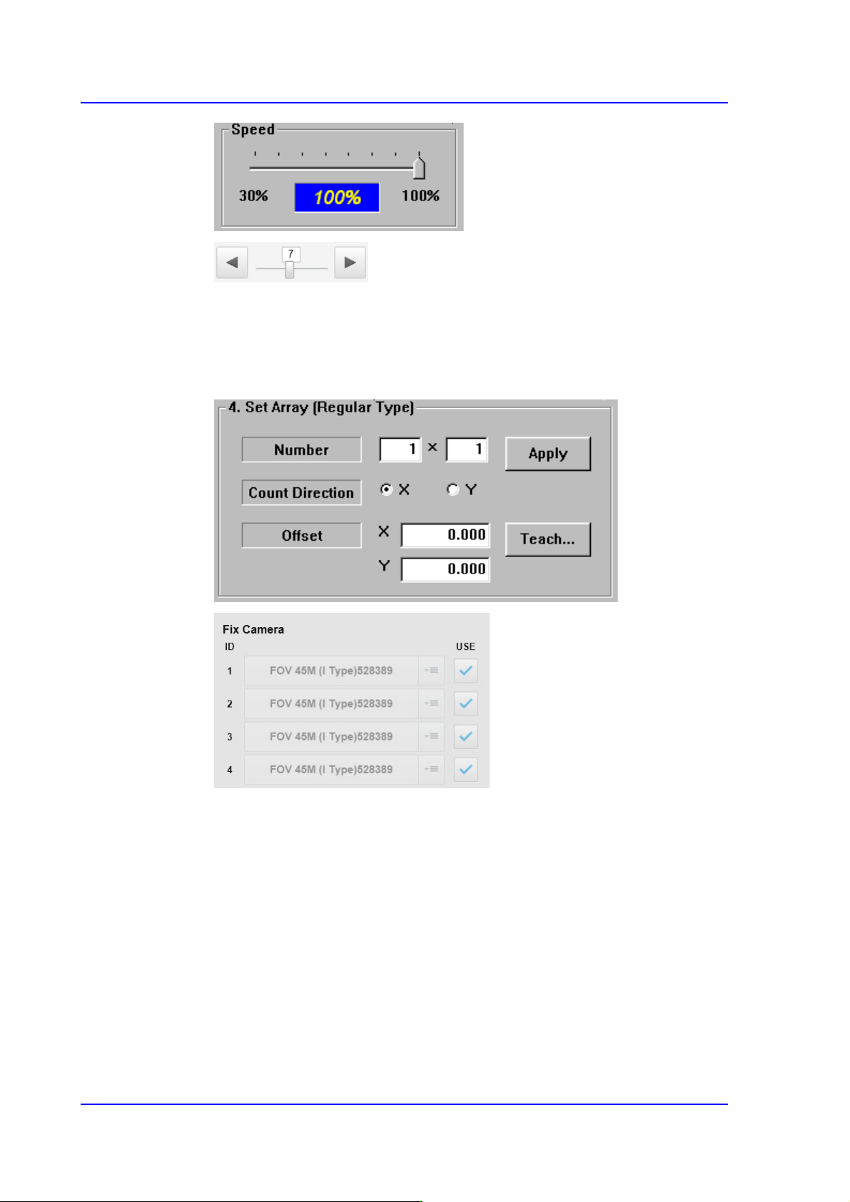
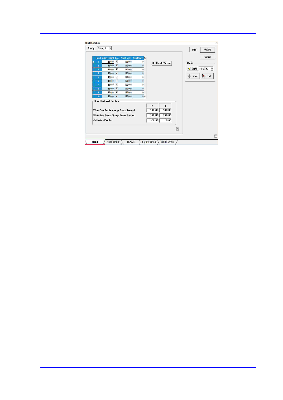
Example: <Set Array [Regular Type].> group / <Fix Camera> group
Tab
When there are several screen in the submenu, selects the tab on the screen to
change the screen. (The following screen shows that the 'Head' tab is selected.)
xxix
Mouse manipulation
The following terms are related to manipulating the mouse.
Click or select
Press once the corresponding item with the left Button of the mouse by moving the
pointer of the mouse.
Double click
Press twice in rapid succession the corresponding item with the left Button of the
mouse by moving the pointer of the mouse.
xxx
Multi-Functional Placer SM482(L) PLUS Administrator’s Guide
Screen display
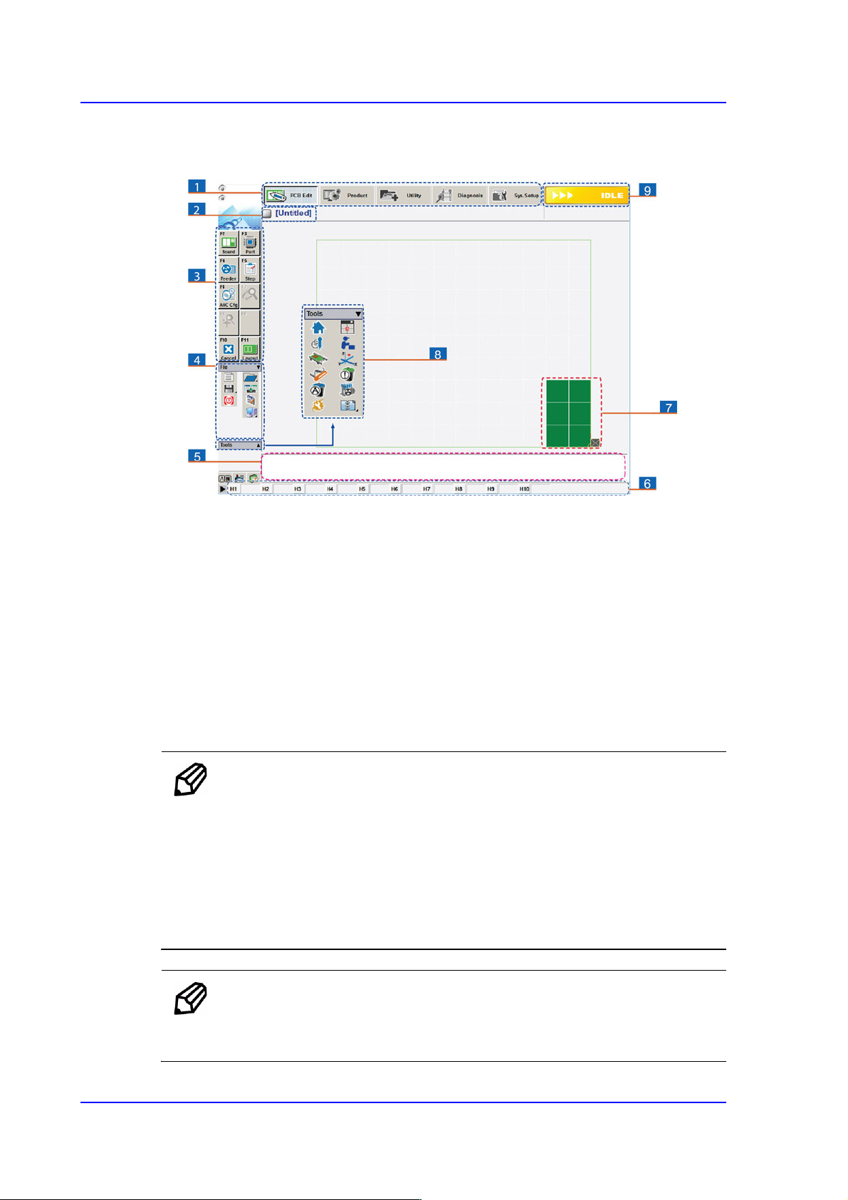
The main screen of MMI of this equipment is shown below.
1: A main menu tool-bar is shown.
2: The PCB file name being worked on is indicated.
3: A sub menu tool-bar is shown.
4: A File menu tool-bar is shown. (New, Open, Save, Merge, Error Message, Window Tool).
5: Events occurring during the operation are displayed.
6: The name of the nozzle, which is inserted in the nozzle-holder of the corresponding head, is
displayed.
7: The shape of the part to be placed is indicated.
8: A Short Cut Bar is displayed. (Home, SM Vision, ANC, Operation Mode, Conveyor, Position Manual
Tool, Dump Information, PM Manager, Telemetry)
9: A help message applicable to the present state as well as the state of the machine (IDLE, RUN,
FREEZE, ADJUST, WAIT, PAUSE, EMER, MPU-STOP) is indicated.
Memo Pictures showing a dialog box or message box of MMI are
inserted to produce this manual. Therefore, the screens shown in
the manual and various settings, values and contents included
within may vary depending on the equipment installed or the
operational environment.
The MMI screens shown in the manual are inserted for more
detailed reference and explanation. They are produced by
enlarging or reducing the contents appearing on the main screen
of MMI.
Memo For a more detailed explanation about the terms used in this manual,
please refer to the 'Guide for SMT's Basic Terms (PDF)' in the web
manual provided by us.