SM482PLUS_Admin(Eng_Ver2.8).pdf - 第473页
15-19 System Setup 4096 for each light level is inputted. <Mapping/T est> button Perform test or automatic mapping for the lig ht level for the camera selected from the <Select Camera> group. Figure15.10 Wh…
15-18
Multi-Functional Placer SM482(L) PLUS Administrator’s Guide
15.4. Light Mapping
Calibrate the brightness of the light for the camera. In order to perform this calibration,
insert the LightFly or LightFix into the No. 1 nozzle of the ANC.
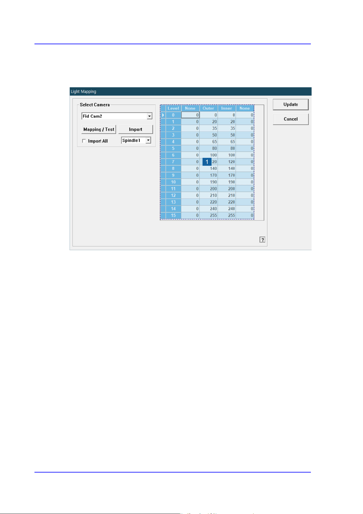
1: Light Level
<Select Camera> combo box
Selection Control
Select the camera to perform light mapping.
Repeat this procedure for all fly cameras and fix cameras.
Light Level group
Sets the brightness by light level.
<Level> column
Dislays 16 steps of lighting.
<Side> / <Outer> / <Inner> column
The value within the range up to 255 for each light level is inputted.
For the Fly Camera
Input the side illumination value within the range of 256 values.
For the Fix Camera
Input the side illumination value within the range of 4096 values.
<Back1> / <Back2> column
Enabled only when the fix camera was selected. The value within the range up to
15-19
System Setup
4096 for each light level is inputted.
<Mapping/Test> button
Perform test or automatic mapping for the light level for the camera selected from the
<Select Camera> group.
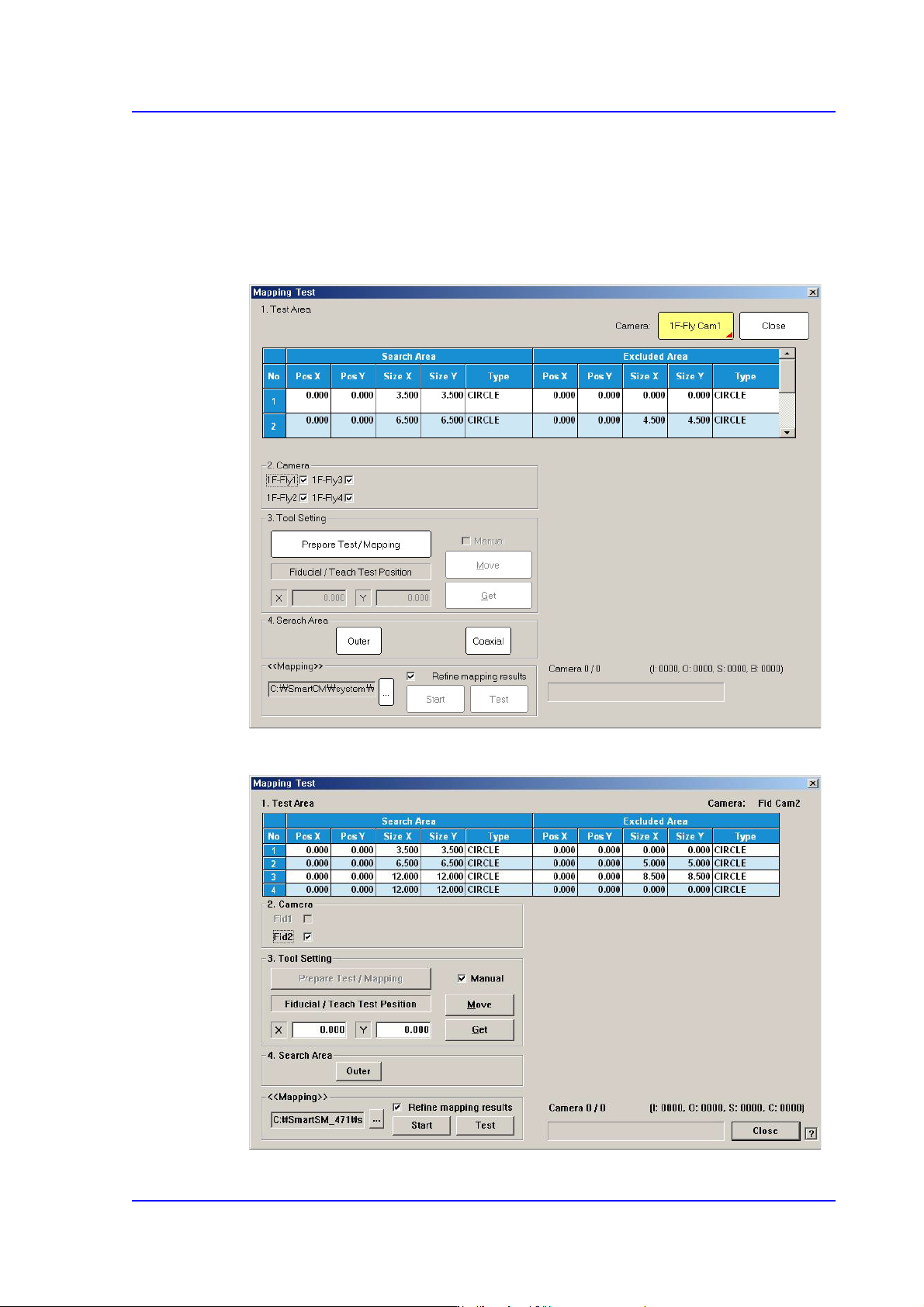
Figure15.10 When the Fly Camera is selected
Figure15.11 When the Fid Camera is selected
15-20
Multi-Functional Placer SM482(L) PLUS Administrator’s Guide
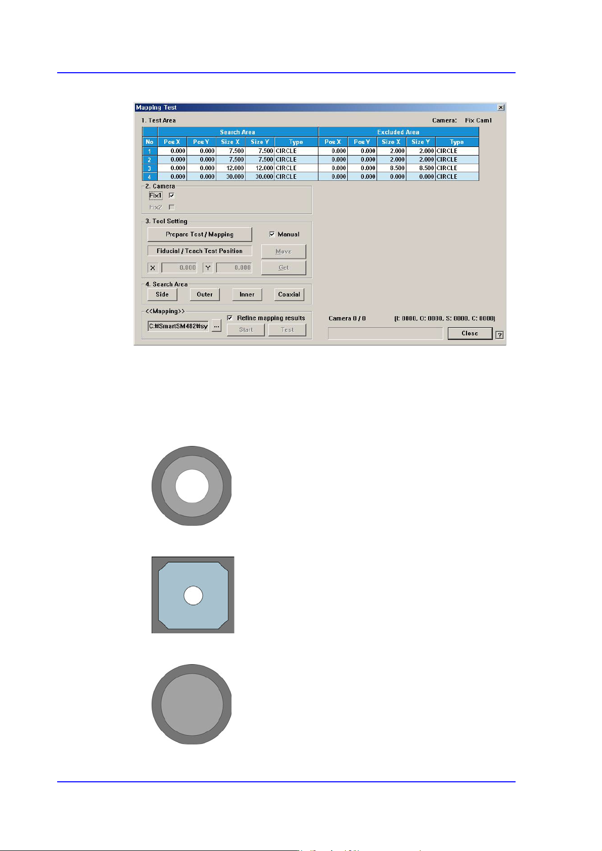
Figure15.12 When the Fix Camera is selected
<1. Test Area> group
Designates the area for which the nozzle for test checks the brightness of the
lighting. The are can be designated up to 4. the search area and excluded area are
designated together. The test area is set automatically. Do not change this value.
Figure15.13 Bottom Shape of Calibration Nozzle for Fly Camera
Figure15.14 Bottom shape of the calibration plate for the Fid camera
Figure15.15 Bottom shape of the calibration nozzle for the Fix camera