SM482PLUS_Admin(Eng_Ver2.8).pdf - 第128页
6-10 Multi-Functional Placer SM482( L) PLUS Administrator’s Guide When a part with lower placemen t priority exists in the first placement area Y ou must set the placement level of the parts if there is any interferenc…
6-9
Board Definition
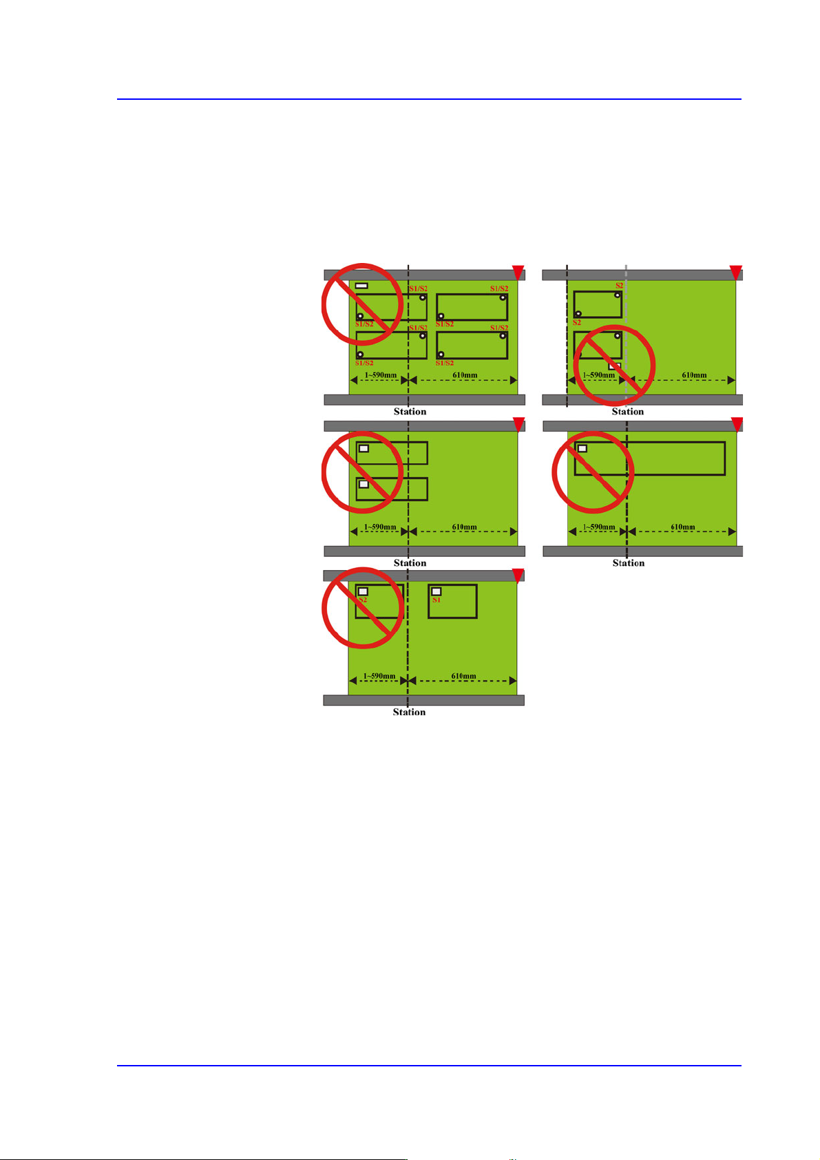
2) When part placement is not possible
When there is a bad/accept mark or a 2D barcode in the
second placement area
If the bad/accept mark or the 2D barcode cannot be
recognized in the first placement area, you cannot use the
bad/accept mark or the 2D barcode.
6-10
Multi-Functional Placer SM482(L) PLUS Administrator’s Guide
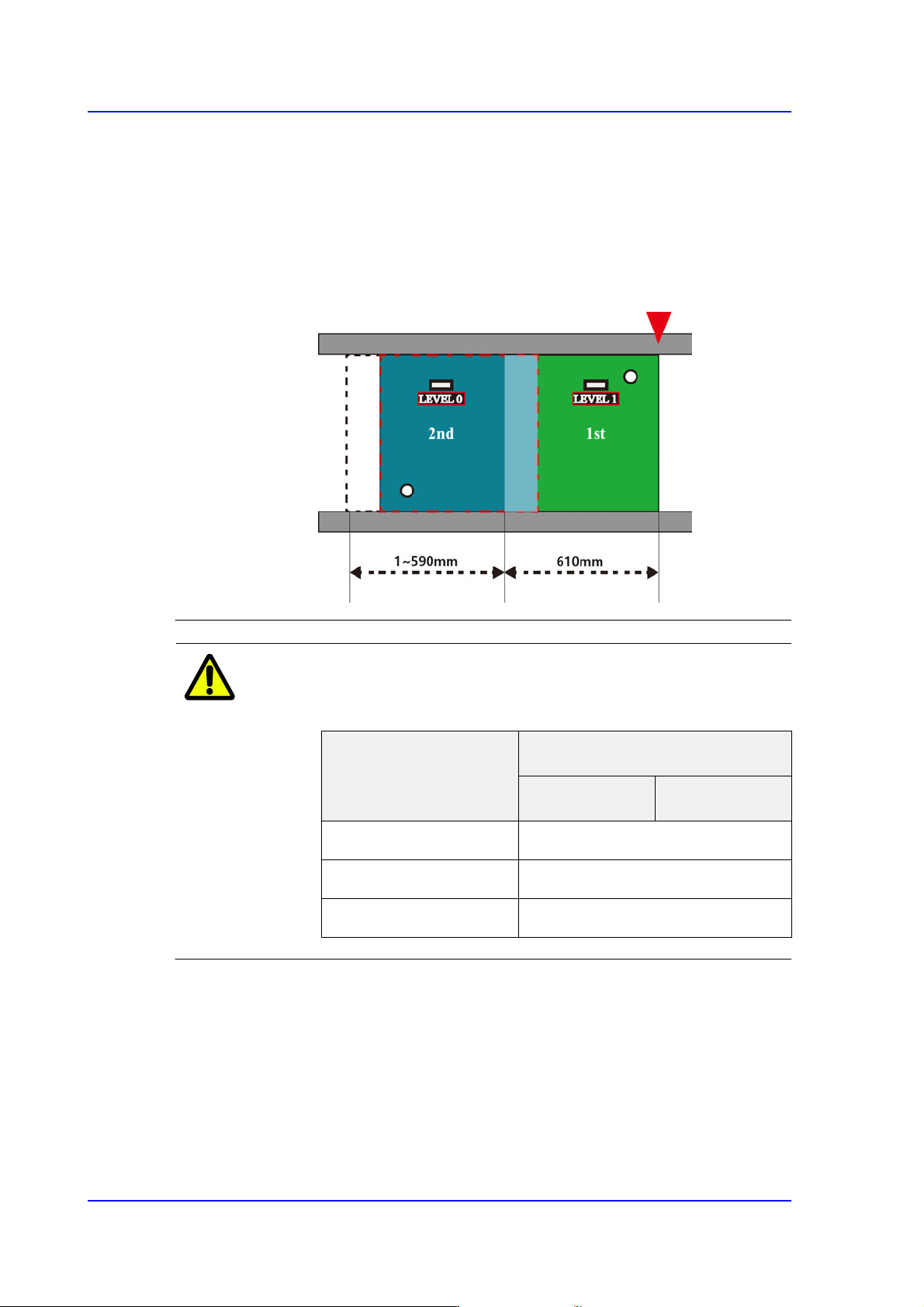
When a part with lower placement priority exists in the first
placement area
You must set the placement level of the parts if there is any
interference with the placed parts nearby depending on the
placement order. When a part with lower placement level
exists in the first placement area, a cycle NG error will occur
and the PCB program cannot be created.
Memo The specifications of the buffer that can be used in the
equipment are as follows.
<8. Handling> group
Set the data necessary for PCB operation.
<Move Z>
After the part is picked up, set the head moving height with the surface of the PCB
being “0” when moving the head.
The default value is 4mm. However, if the placed part height is higher than 4mm,
input the height part in mm unit when it is placed on the PCB.
Category
Buffer(Board) Size
Entry Zone Exit Zone
L460mm, L510mm ~ L460mm
L610mm, L660mm 610mm / 660mm
L1,200mm 540mm
6-11
Board Definition
The height cannot be set to a value less than 4 mm. The height can be inputted up
to 12 mm. As this value becomes greater, the working time becomes longer.
Therefore, set the height to optimum value.
Caution Move Z is installation height, the test PCB shall not hang
down.
If teaching is done without checking whether a nozzle is
mounted on the Head,
the minimum movement height of head becomes low and
the head and the transport rail might collide.
Since the Z axis moving height is different for each
machine, the same value cannot be set for all machines.
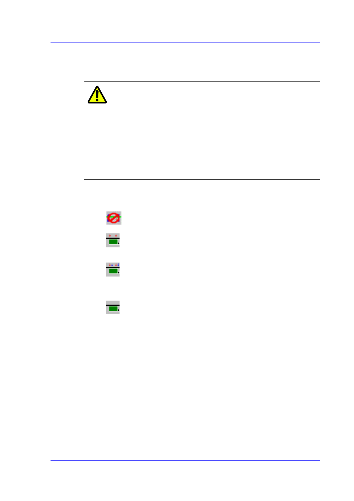
<Fix Type> combo box
Select the method for fixing a PCB.
Default: A method of fixing the PCB by moving up backup table.
Edge Fixer: A method of arrangement by pushing the PCB from the side
with a device attached on the conveyor.
Edge Fixer2: It is the same as the “Edge Fixer” method, but it is a method of
pushing twice from the side. If the PCB weight is greater than 1kg, select the
‘Edge Fixer2’
None: It uses only the PCB clamping method for fixing a PCB.
<PCB In> button
Loads the PCB in the operation area.
<PCB Out> button
Out the PCB in the operation area.
<PCB Unlock> button
Release the PCB fixed in the operation area.
<Stopper U/D> button
Moves up or down the work stopper, the stopper of PCB in the operation area.
<BUT U/D> button
Moves up or down the BUT (Back Up Table) that locks up the PCB in the operation
area.