SM482PLUS_Admin(Eng_Ver2.8).pdf - 第191页
7-19 Part Registration <Polarity Direction> combo box Selects the direction of the polarity . Figure7.4 Polarity Posi tion (Triangle ) Figure7.5 Polarity Posi tion (Line ) <Reel T ype> combo box Selects t…
7-18
SM PLUS Administrator’s Guide
-Etc
Selected when displaying only the nozzles other than CN, Special
nozzles in the following list box.
<Recommended> List Box
Displays the nozzles recommended for the corresponding part.
<All> List Box
Displays the nozzles conforming to the conditions selected from the
<Filter> combo box.
<Selected Nozzle> List Box
Displays the registered nozzles so that they can be used for part pickup.
The nozzle information set here is used to perform optimization later.
The priority in applying nozzles is determined according to the order in
which nozzles are set.
button
Adds the nozzles in the left <Recommended> list box or <All> list box to
the <Selected Nozzle> list box.
Register the selected nozzles as a nozzle to be used for part pickup.
button
Adds the nozzles selected from the right <Selected Nozzle> list box to the
left <Recommended> list box or <All> list box.
Performs setup so that the selected nozzles will not be used for part
pickup.
‘Setup of Other Options’ area
Set the part polarity, tape reel type, pickup angle of the part supplied from a feeder.
<Polarity Type> combo box
Selects the polarity type. The types that can be selected are as follows:
Selected in case of a Lead/Ball part.
Line: Selected in case of a chip part. (TR part is excluded)
7-19
Part Registration
<Polarity Direction> combo box
Selects the direction of the polarity.
Figure7.4 Polarity Position (Triangle )
Figure7.5 Polarity Position (Line )
<Reel Type> combo box
Selects the tape reel type of the tape feeder.
<Part R> combo box
If the direction of part supply from the feeder is different from the part direction
when the part was registered, sets the angle at which the part supplied from the
corresponding feeder is picked.
In order to prevent the occurrence of a part recognition error, the part direction
when the part was registered must be the same as the direction when the part was
picked up by applying part R.
7-20
SM PLUS Administrator’s Guide
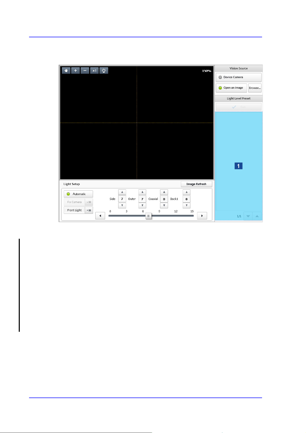
7.2.2.2. SETUP CAMERA
Sets the lighting value of the camera recognizing a part.
1: Thumbnail Image
<Vision Source> group
Selects the source of a vision image.
<Device Camera> switch Button
Selected in cases to used the camera image of the Parts registration device as the
source of the vision image.
<Open an image> switch Button
Selected in cases to use the saved part image as the source of the vision image.
<Browse...> button
Enabled only when the <Image open> switch button is selected. Executes the
dialog box so that the saved part image can be selected.
<Light Level Preset> area
It is possible to view a part image at the lighting value recommended depending on the
part group selected from the <Part Category> group.
<Run> button
Captures the part image according to the recommended lighting value and shows it
in the 'Thumbnail Image' area.