SM482PLUS_Admin(Eng_Ver2.8).pdf - 第312页
10-8 Multi-Functional Placer SM482( L) PLUS Administrator’s Guide <Prohibited> list box For the feeder base slot in which no device is desired to be arranged, click the arrow button ( ) to move it to the <P ro…
10-7
Optimization
10.3. Feeder Lane
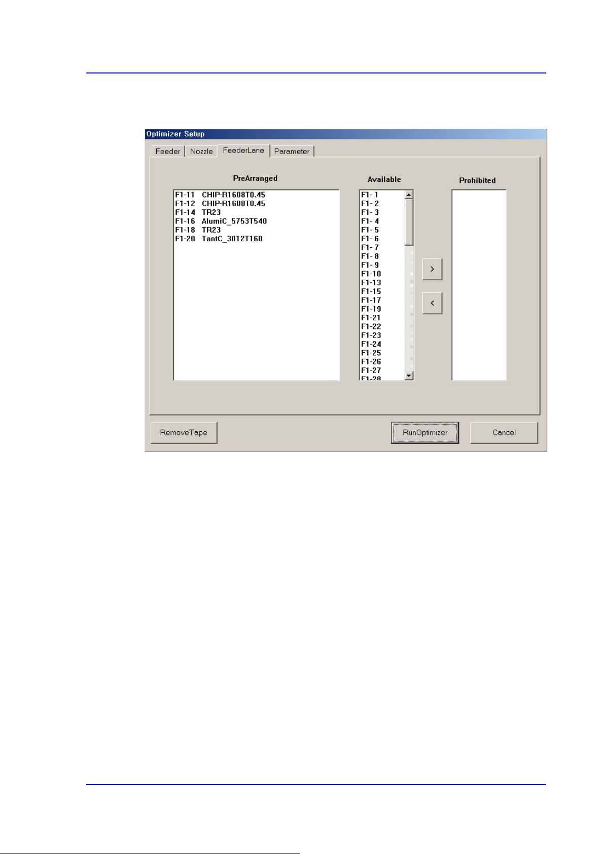
Figure10.4 “Optimizer Setup: Feeder Lane” dialog box
This dialog box to set the feederbase slot to be used for feeder arrangement by the
Optimizer. The devices that can be arranged on the feederbase slot include tape feeder and
stick feeder unit.
Current status of feeder arrangement in the feeder base slots is indicated. If the optimizer
cannot arrange the devices due to a defective feeder base slot or for other reasons, the
feeder base slot that must not be arranged can be designated.
<PreArranged> list box
Indicates the arrangement status of feeders currently installed in the feeder base slots.
Of the feeder base slot number, ‘F’ refers to the front feeder base and ‘R’ the rear
feeder base
For parts which are transferred to the tape feeder, a part name is indicated after the
number of the slot in which the feeder is installed. For stick feeder or tray feeder,
corresponding feeder type is indicated. In addition, the slot of the feeder base that
cannot be used due to interference with other devices is indicated by a dotted line.
<Available> list box
Displays the feederbase slot where devices can be arranged in the Optimizer.

10-8
Multi-Functional Placer SM482(L) PLUS Administrator’s Guide
<Prohibited> list box
For the feeder base slot in which no device is desired to be arranged, click the arrow
button ( ) to move it to the <Prohibited> list box group.
The optimizer arranges no device in the feeder base slot indicated in the <Prohibited>
list box. Clicking the arrow button ( ) can undo the command.
The optimizer arranges the devices considering the interference between the devices
that are arranged as feeder base slots or which will be newly arranged.
10-9
Optimization
10.4. Setup Menu /Parameters
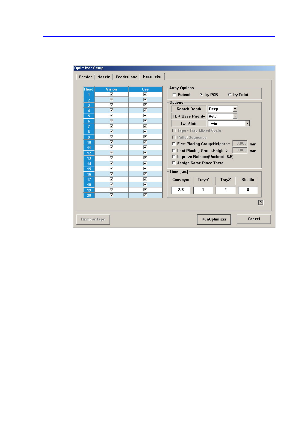
Figure10.5 “Optimizer Setup: Parameters” tab dialog box
This dialog box to set the options and parameters for the Optimizer execution.
<Head> check box group
Sets whether to use for each head.
<Use> check box
The “Use check box” indicates whether to use the corresponding head. For
example, when it is difficult to perform work if Head 3 has a problem, select the
check box of Head 3 and leave it blank.
Doing so, the optimizer will create a job program with the head except for the one
whose use is suspended. If all heads to be used are stopped, the optimizer cannot
perform optimization.
<Array Options> group
Used when designate display method and optimization option of the MMI step
program when editing the array PCB.
<Extend> check box
In case of array PCB, <Extend> check box can be ticked. Then, MMI performs
optimization considering one array PCB includes all the array installation
positions. Accordingly, work efficiency is improved.