SM482PLUS_Admin(Eng_Ver2.8).pdf - 第250页
7-78 SM PLUS Administrator’s Guide <X Offset> edit box It is possible to set the X of fset. <Y Offset> edit box It is possible to set the Y of fset. <Z Offset> edit box It is possible to set the Z…

7-77
Part Registration
Not Use: Set this function so that it is not used.
Pick: Set this function so that it is used only for pickup.
Mount: Set this function so that it is used only for placement.
Pick&Mount: Set this function so that it is used only for pickup and
placement.
Caution In case of shock sensitive components like CSP or μBGA,
the z-axis related speed parameters must be set according
to the component manufacturer’s specification or standards.
And use the nozzle suitable to component manufacturer’s
specification or standards.
If necessary, please contact our Business Department or
the local agent for the nozzle suitable to component
manufacturer’s specification or standards.
<Force Control Type> selection box
Select the method to control the force imposed on the part when the head spindle
moves down for part pickup or placement.
This function is supported for machines equipped with a head module that
provides a force control function.
Not Use
Selected in cases to setup so the force control function will not be used.
Pickup
Selected in cases to setup so that the force control function will be applied
only for part pickup.
Place
Selected in cases to setup so that the force control function will be applied
only for part placement.
Both
Selected in cases to setup so that the force control function will be applied
only for part pickup and placement.
<Max. Force (g)> edit box
Input the maximum force controlled by the head module.
If a PIP part is not inserted into a PCB hole by 1 kg of force, perform a PIP part
insert test by increasing the force by 500g each time.
<Place Offset> group
It is possible to set the part placement offset.
7-78
SM PLUS Administrator’s Guide
<X Offset> edit box
It is possible to set the X offset.
<Y Offset> edit box
It is possible to set the Y offset.
<Z Offset> edit box
It is possible to set the Z offset.
<R (Place Angle> edit box
It is possible to set the R offset.
<ETC> tab
<Flux Type> selection box
Selects the method for flux part recognition. This function can be used for the
machine equipped with a flux device.
No Flux
Selected when the part is not a flux part. If this option is selected, the POP
function cannot be used.
Post Flux
Selected in cases to recognizes a part after dipping it into flux.

7-79
Part Registration
Pre Flux
Selected in cases to dips a part into flux after recognizing it.
<Flux Depth> edit box
Selects the depth of part dipping into flux. Set the depth based on '0' according to
the properties of the part.
<Flux Thickness> edit box
Input the thickness of the flux film formed on the table.
<Flux Dipping Time> edit box
Input the period of time during which a part remains dipped in flux. The default
value is 0.2000 and its range is 0.1000~5.000.
<Flux Dipping Inspect> check box
Recognizes the shape of flux applied on the balls of BGA parts.
<Flux Min Ratio(%)> edit box
Sets the ratio of the minimum allowable area of flux recognized by the Vision
against the ball area.
<Flux Max Ratio(%)> edit box
Sets the ratio of the maximum allowable area of flux recognized by the Vision
against the ball area.
<Flux Brightness> edit box
Sets the brightness of flux recognized by the Vision.
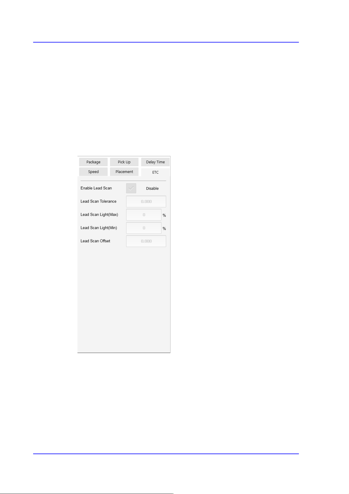
<Enable lead scan> check button
Selected when inspecting the leads of an IC part. This function can be used only
for machines equipped with a lead scanner.
<Lead Scan Tolerance> edit box
Input the value that allows the extent by which a lead deviates from the normal
pattern. It is indicated in mm. If the difference in the height of two neighboring
leads is greater than this value or a specific lead deviates from this value when it is
assumed that the inclination of each lead is straight line, the corresponding part is
judged to be defective.
<Lead Scan Gain> edit box
Sets the gain of the light receiving section for the laser spot beam. In general, set
this value to '2'.
<Lead Scan Offset> edit box
Even if it is possible to input and use an offset at the position calculated for lead
scanning, generally set it to '0'.