SM482PLUS_Admin(Eng_Ver2.8).pdf - 第147页
6-29 Board Definition the <Y> edit box of <7. Search Area>. <8. Score> group Edit box The “score” is the numericalized value th at inc ates how accura tely the inspected fiducial mark corresponds to…
6-28
Multi-Functional Placer SM482(L) PLUS Administrator’s Guide
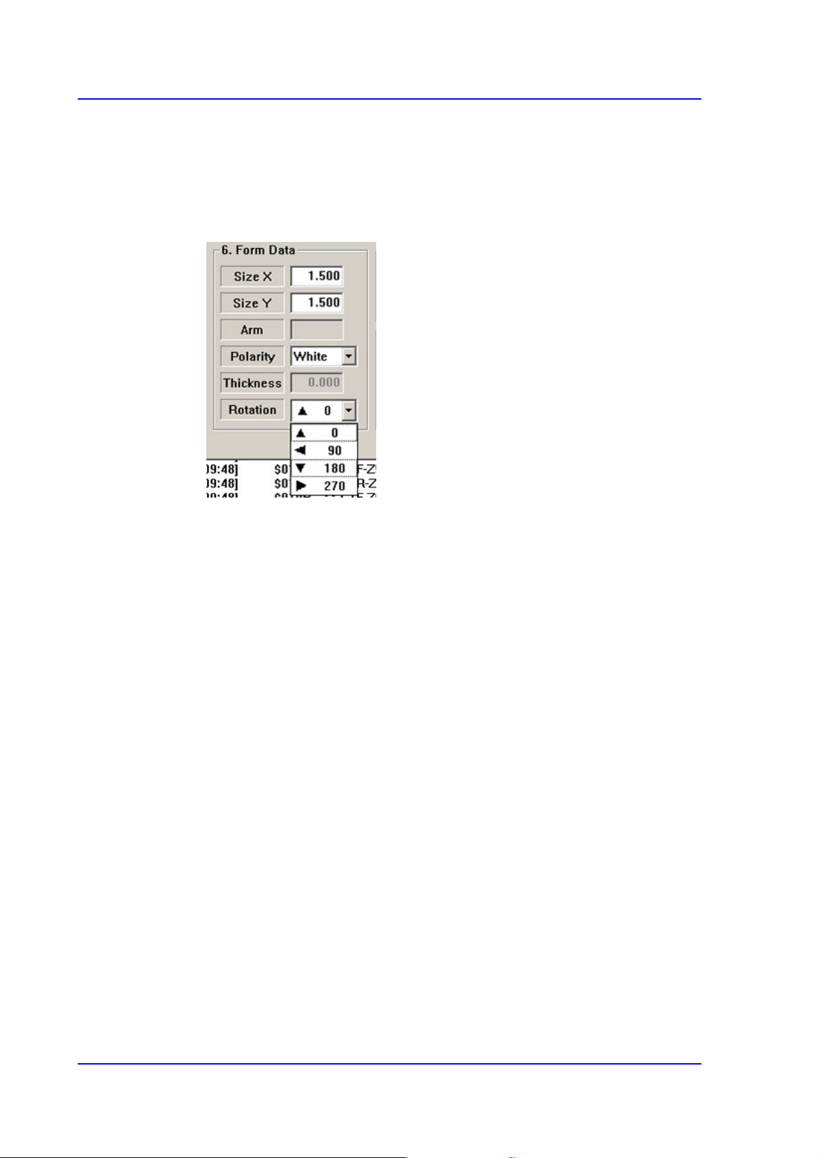
<Rotation> combo box
Select the rotation angle of fiducial mark. In the case of triangles, the registered
form has the corner facing upward, but there are occasions where the corner is
actually facing sideways.
In those cases, select the rotation angle.
0: the angle of the mark is 0.
90: the mark is rotated to 90.
180: the mark is rotated to 180.
270: the mark is rotated to 270.
<7. Search Area> group
Set the area in which to search the fiducial mark. The main purpose of this feature is to
limit the search range for when there are forms similar to the mark near the mark such
that they can interfere with recognition on certain PCBs.
<X> edit box
Set the position to start searching for the fiducial mark in X axis. The center of
SMVision is zero (0), and is generally setup as the size of negative (-)value in the
X direction fiducial mark.
<Y> edit box
Set the position to start searching for the fiducial mark in Y axis. The center of
SMVision is zero (0), and is generally setup as the size of negative (-)value in the
Y direction fiducial mark.
<Width X> edit box
Set the value of search range in X axis. Generally setup as twice the value setup in
the <X> edit box of <7. Search Area>.
<Width Y> edit box
Set the value of search range in Y axis. Generally setup as twice the value setup in
6-29
Board Definition
the <Y> edit box of <7. Search Area>.
<8. Score> group
Edit box
The “score” is the numericalized value that incates how accurately the inspected
fiducial mark corresponds to the set data. This “score” has a value between 0 and
1000 points. The value to be set in the <Score> indicates at least how much the
“score” value must be if it can be recognized as set data.
Basically, it must be greater than 600 (default value) for correct compensation.
Even in the worst case, it must be greater than 300. If there is a mark of different
shape with similar size in the vicinity (recognition area) of the fiducial mark to be
recognized, the score value must be set high (greater than at least 600).
<9. Light> slide bar
Set the light value when the fiducial mark is inspected. In general, 7 is appropriate but
it can be adjusted according to the condition of PCB and fiducial mark.
<Tuning> button
Obtain the size of fiducial mark actually recognized by MMI using the fiducial mark
data. Perform tuning using the vision system in order to minimize the mark
measurement error.
That is, it means that the machine measures the measurement error again. Use this for
the accurate correction of the fiducial marks.
In general situations, the fiducial mark is not measured individually and the
coordinates of the fiducial mark are created after setting the PCB on the conveyor.
Input the approximate size (by visual judgment) and check the image mark deviation
between the actual mark and the image mark in the data through the SMVision
window to perform recorrection.
In this case also, more accurate correction can be made by performing measurement
through tuning. This function is executed until the actually measured new data
becomes equal to the inputted data.
<Outline/Real> button
Shows the image seen through the Vision in real display to which threshold is not
6-30
Multi-Functional Placer SM482(L) PLUS Administrator’s Guide
applied, or in the image (Binary) to which threshold is applied as recognized by MMI.
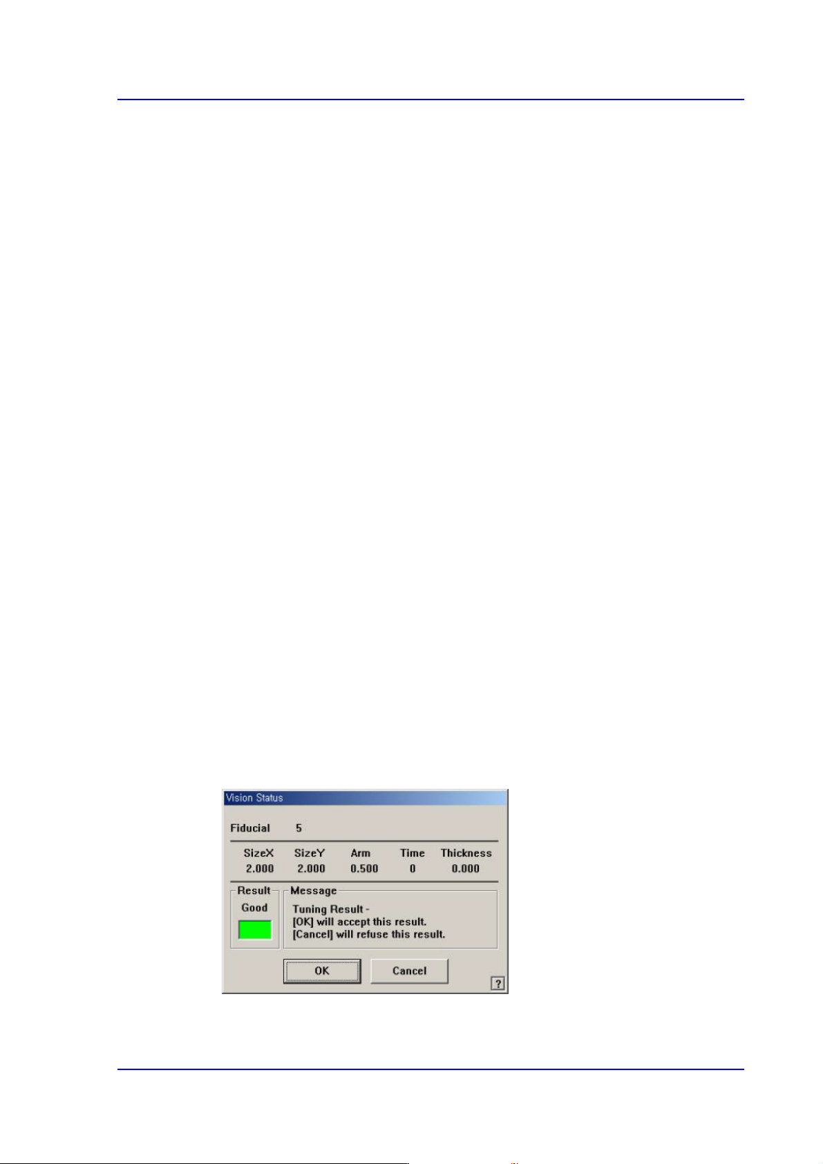
<Test> button
By using the registered mark information, tests the fiducial mark.. The accuracy of the
registered mark data can be verified. When the test is successful, the following
message box is displayed.
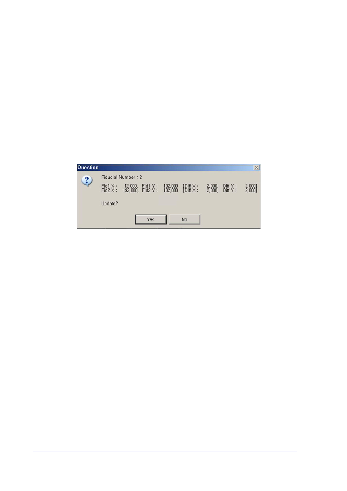
<Scan> button
Executes a scan test on the set fiducial mark. Mark recognition is performed to
minimize the teaching offset for the center points (2 points) of the fiducial mark.
Move the fiducial camera to the position of the set coordinate and recognize the mark.
After recognition of the mark, the offset is indicated as shown in the following figure.
When it is desired to compensate the offset, select “Yes”.
When placing the IC part whose lead pitch is 0.5, use this function to perform
compensation for the fiducial mark.
<OK> button
Saves the fiducial mark data and closes the <Fiducial Position & Mark> dialog box.
<Cancel> button
Closes the <Fiducial Position & Mark> dialog box without saving the fiducial mark
data.