SM482PLUS_Admin(Eng_Ver2.8).pdf - 第272页
8-20 Multi-Functional Placer SM482( L) PLUS Administrator’s Guide <T each> group Used for moving the selected object to th e assigned position of co ordinates by rotating XY axis driving motor , or for obtaining …
8-19
Feeder Setup
0: Not installed on any feeder base.
1: Installed on Feeder Base (Front Feeder Base) 1.
2: Installed on Feeder Base (Rear Feeder Base) 2.
2. <Slot No.>
Displays the slot number of the feeder base where the corresponding stick unit is
installed currently. The numbers displayed are as follows.
0: Not installed in any slot.
1 - 52: Installed in the corresponding number slot.
3. <Change…> button
In the case of installing stick unit to the feeder base, change the feeder base unit
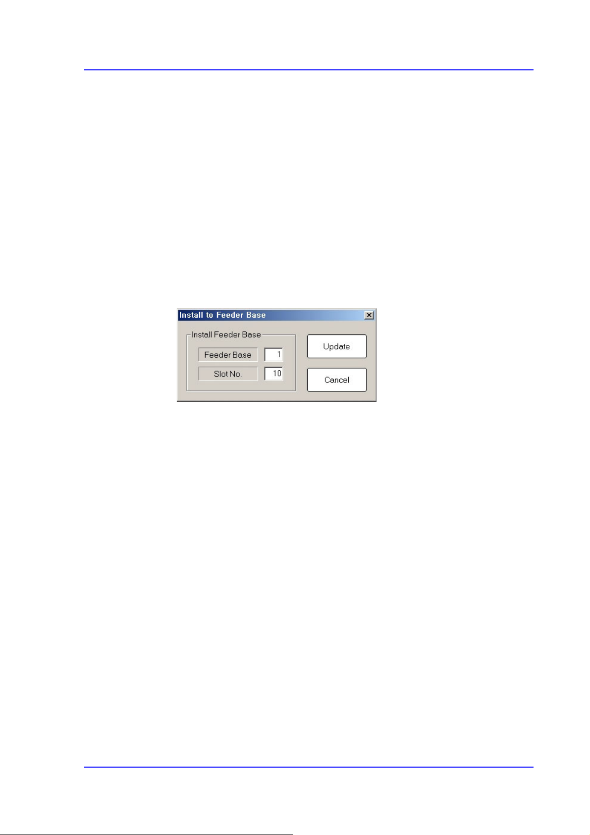
and slot number to install. When this Button is clicked on, the following dialog
box is displayed.
<Install Feeder Base> group
Feeder Base
Displays the feeder base where the corresponding stick unit is installed
currently. The numbers displayed are as follows
0: Not installed on any feeder base.
1: Installed on Feeder Base(Front Feeder Base)1.
2: Installed on Feeder Base(Rear Feeder Base)2.
Slot No.
Designates the order in which the stick feeder is installed.
<Update> button
Saves the set contents and closes the dialog box.
<Cancel> button
Closes the dialog box without saving the set contents.
8-20
Multi-Functional Placer SM482(L) PLUS Administrator’s Guide
<Teach> group
Used for moving the selected object to the assigned position of coordinates by rotating
XY axis driving motor, or for obtaining the present coordinates of the selected object.
Button
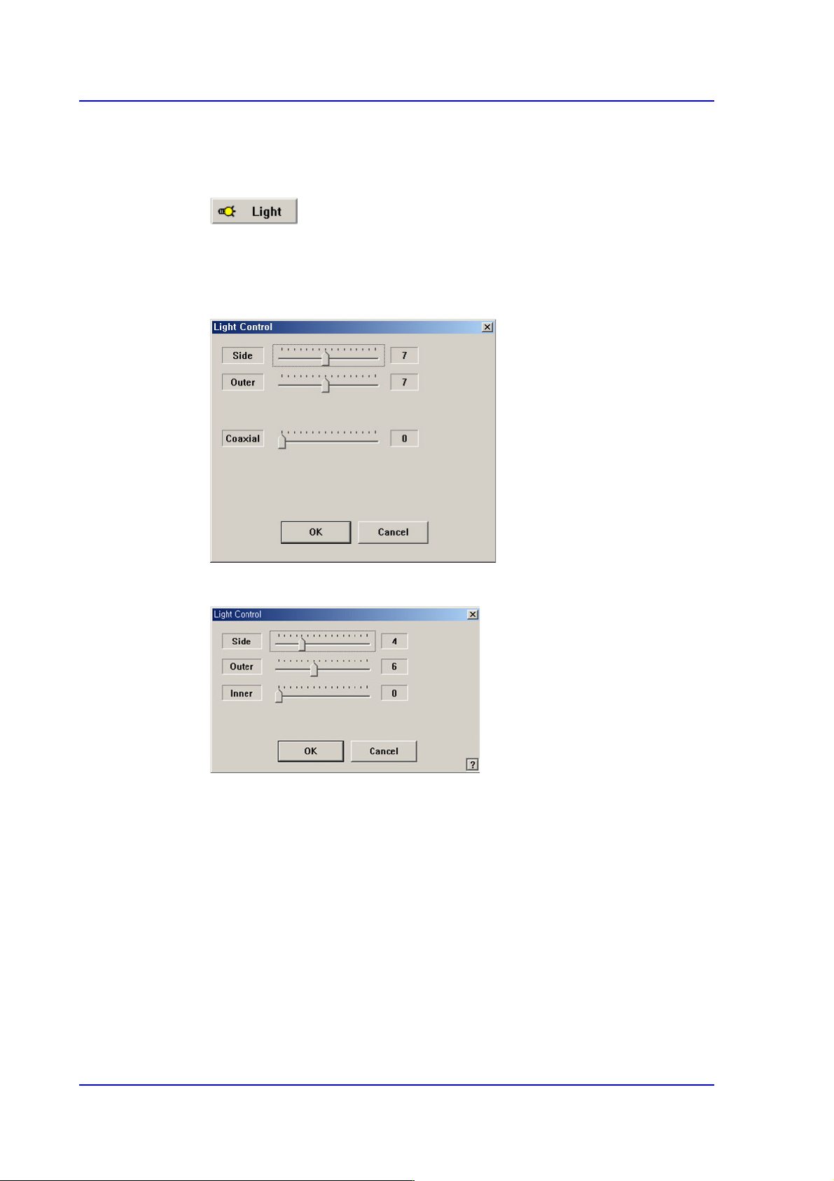
Setup illumination of fiducial camera to be used for teaching. When this Button is
clicked on, the following dialog box is displayed.
Figure8.8 “Camera No. =Head Camera“ dialog box
Figure8.9 “Camera No. =Fix Camera“ dialog box
<Side> slide bar
Set a value for the side light. (0 –15)
<Outer> slide bar
Set a value for the outer light. (0 - 15)
<Inner> slide bar
Set a value for the outer light. (0 - 15)
<OK> button
Saves the set light value and closes the dialog box.
<Cancel> button
Closes the dialog box without saving the set light value.

8-21
Feeder Setup
Table8.1 Use of the Fix Camera Lighting
Combo Box
Used for selecting the object to move to the designated coordinates by rotating the
XY axis driving motor or to select the object for which the present coordinates is
searching. Selectable objects are as follows:
Fid Cam (Option): Selects the fiducial camera of the head.
Head 1 ~ Head 6: Selects the Head #1~Head #6
<Move> button
Move the object selected in the Combo Box to the position of the assigned
coordinates. Before executing <Move> button, the cell in the grid(Coordinates for
pickup point of stick feeder) corresponding to the desired position must be clicked
on.
<Get> button
Obtain coordinates for XY axis with reference to the object selected in the Combo
Box. At this time, Before executing <Get> button, the cell in the grid (Coordinates
for pickup point of stick feeder) corresponding to the desired position must be
clicked on.
<Pick> button
Picks up parts from the presently selected stick feeder. At this time, the head (Device)
to pickup the part must be selected first. When the pick-up is successful, the following
dialog box is displayed.
Please refer to“8.1.1 Feeder Base” of <Pick> button for more information.
<2Pt. Teach…> button
When teaching the pick-up position of the stick feeder, the center point is calculated
by teaching two corner points at opposite angles of the pocket with the component.
Please refer to “8.1.1 Feeder Base” of <2Pt. Teach…> button for more information.
Light Use Applicable Part Remarks
Side Lights the edge of a part Chip, QFP, BGA, SOP etc
Outer Lights round edge of a
part or part surface
Chip, QFP, BGA, SOP etc
Inner Lights a part surface Chip, QFP, BGA, SOP etc