SM482PLUS_Admin(Eng_Ver2.8).pdf - 第396页
14-24 Multi-Functional Placer SM482( L) PLUS Administrator’s Guide 14.3. Calibration [F9] Only fix camera is activated. Used for setting up the position of the fiducial mark of the fix camera located at the upper part of…

14-23
Machine Calibration
corresponding to the desired position must be clicked on with a mouse.
<Get> button
Obtain coordinates for XY axis with reference to the object selected in the combo
box. At this time, before executing <Get> button, the fix camera corresponding to
the desired position must be clicked on with a mouse.
<Position Data> group
Set the position of the fix camera.
<X> edit box
Set the X position value of the fix camera.
<Y> edit box
Set the Y position value of the fix camera.
14-24
Multi-Functional Placer SM482(L) PLUS Administrator’s Guide
14.3. Calibration [F9]
Only fix camera is activated. Used for setting up the position of the fiducial mark of the fix
camera located at the upper part of ANC.
The following are the works to be performed before performing calibration or those to be
performed in advance.
I/O Test
Mirror offset check and correction
Nozzle check and vacuum check option for system constant
ANC type check
Pneumatic system check for any problem
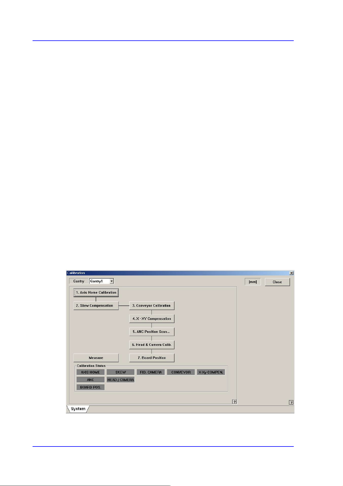
The order in which the calibration is performed and the calibration tool needed to perform
the corresponding calibration is as follows;
Axis Home Calibration
Skew Compensation
Fiducial Camera Scale Calibration
Conveyor Calibration
X-XY Compensation – Calibration Bar
ANC Fiducial Mark Teaching
Head & Camera Calibration - CN040, CNT20, Light Fly/Light Fix Nozzle,
Calibration Tool
14-25
Machine Calibration
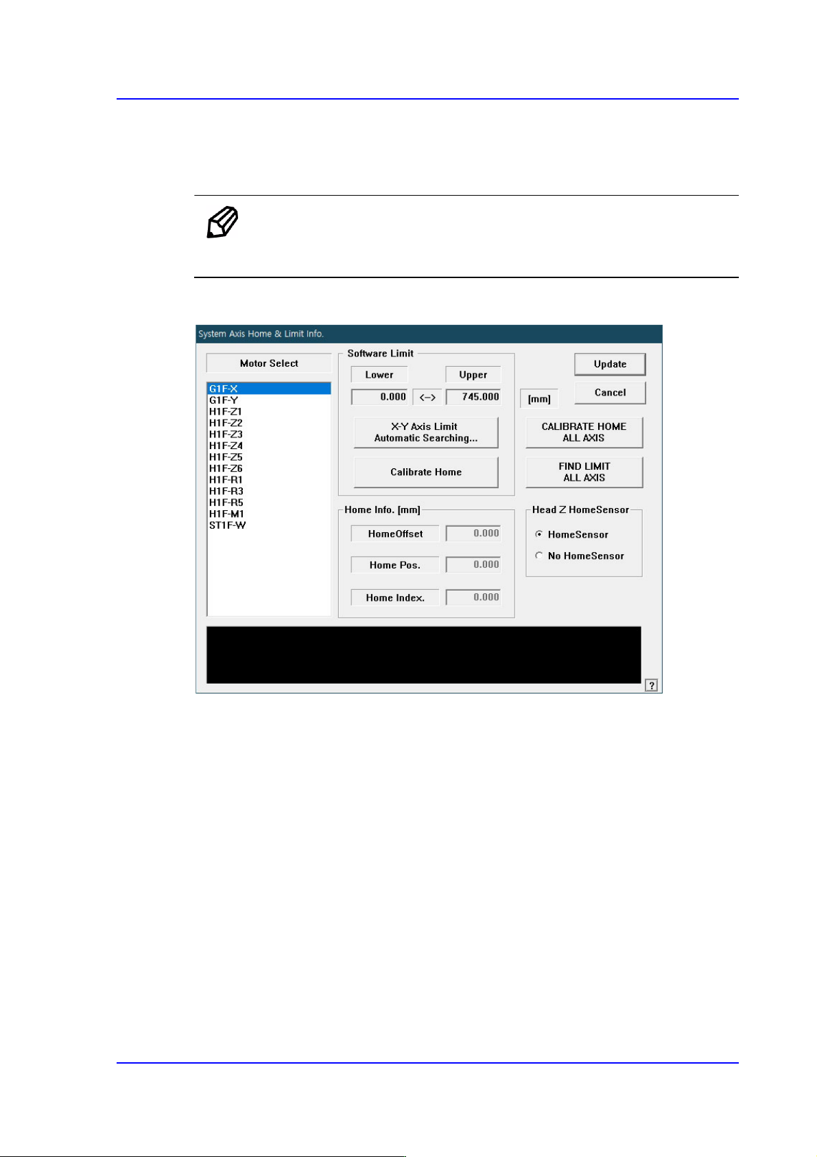
14.3.1. Axis Home Calibration
Sets the limit position of each axis to move. When this button is clicked on, the following
dialog box is displayed.
Memo In order to access this menu, the user must execute login with
authorization from the ‘Service Engineer’.
Figure14.8 “System Axis Limit Info.” dialog box
<Motor Select> list box
Select the motor axis for which to set the limit. Available axes are as follows.
G1F-X: X axis of the front gantry
G1F-Y: Y axis of the front gantry
H1F-Z1: Z axis of head 1 of the front gantry
H1F-Z2: Z axis of head 2 of the front gantry
H1F-Z3: Z axis of head 3 of the front gantry
H1F-Z4: Z axis of head 4 of the front gantry
H1F-Z5: Z axis of head 5 of the front gantry
H1F-Z6: Z axis of head 6 of the front gantry
H1F-M1: Mirror axis of the front gantry
H1F-R1: Theta axis (H1, H2) of the front gantry