SM482PLUS_Admin(Eng_Ver2.8).pdf - 第432页
14-60 Multi-Functional Placer SM482( L) PLUS Administrator’s Guide 6. The message “Calibration is Pr epared. T o Calibrate, Click [Next]” appears. At this time, click the <Light…> butto n and adjust the brightness …
14-59
Machine Calibration
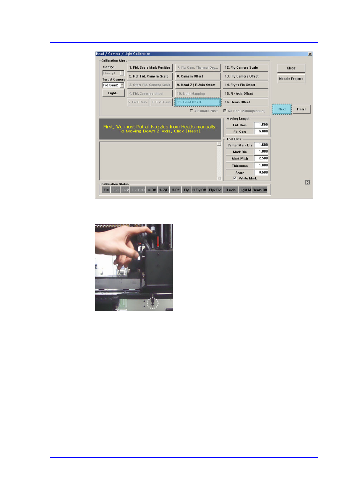
3. Then, after the head assembly moves to the designated position, move all Z-axes
down. At this time, remove all inserted nozzles manually.
4. Then the message “Next Attach the Calibration Tool to Head 1. Click [Next] for
Moving Down Head. After Moving, Attach the tool to head Manually” appears. Click
the <Next> button after inserting the calibration tool in the CNT20 nozzle at nozzle-
holder of Head #1 manually.
5. The message, “Move To Center Position of [Fix 1] Camera. To Move, Click [Next]” is
displayed in the message window. Click the <Next> button to move the head assembly
to the center of the Fix 1 Camera.
14-60
Multi-Functional Placer SM482(L) PLUS Administrator’s Guide
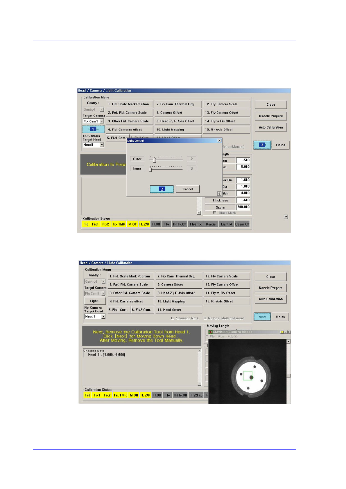
6. The message “Calibration is Prepared. To Calibrate, Click [Next]” appears. At this
time, click the <Light…> button and adjust the brightness of the light in the ‘Light
Control’ dialog box so that the fiducial mark on the calibration tool that is seen in the
‘SMVision’ window can be seen clearly. Then click the <Next> button.
7. The calibration is performed automatically. If it is completed, the calibration result is
displayed as shown in the following figure. Click the <Next> button.
14-61
Machine Calibration
8. Then the message “Next, Remove the Calibration Nozzle From Head 1. Click [Next]
for Moving Down Head. After Moving, Remove the Nozzle Manually” appears. Click
the <Next> button to remove the calibration tool from the nozzle-holder of Head #1
manually.
9. Form Head #2 to Head #6, perform calibration in the same manner as it was performed
for Head #1.
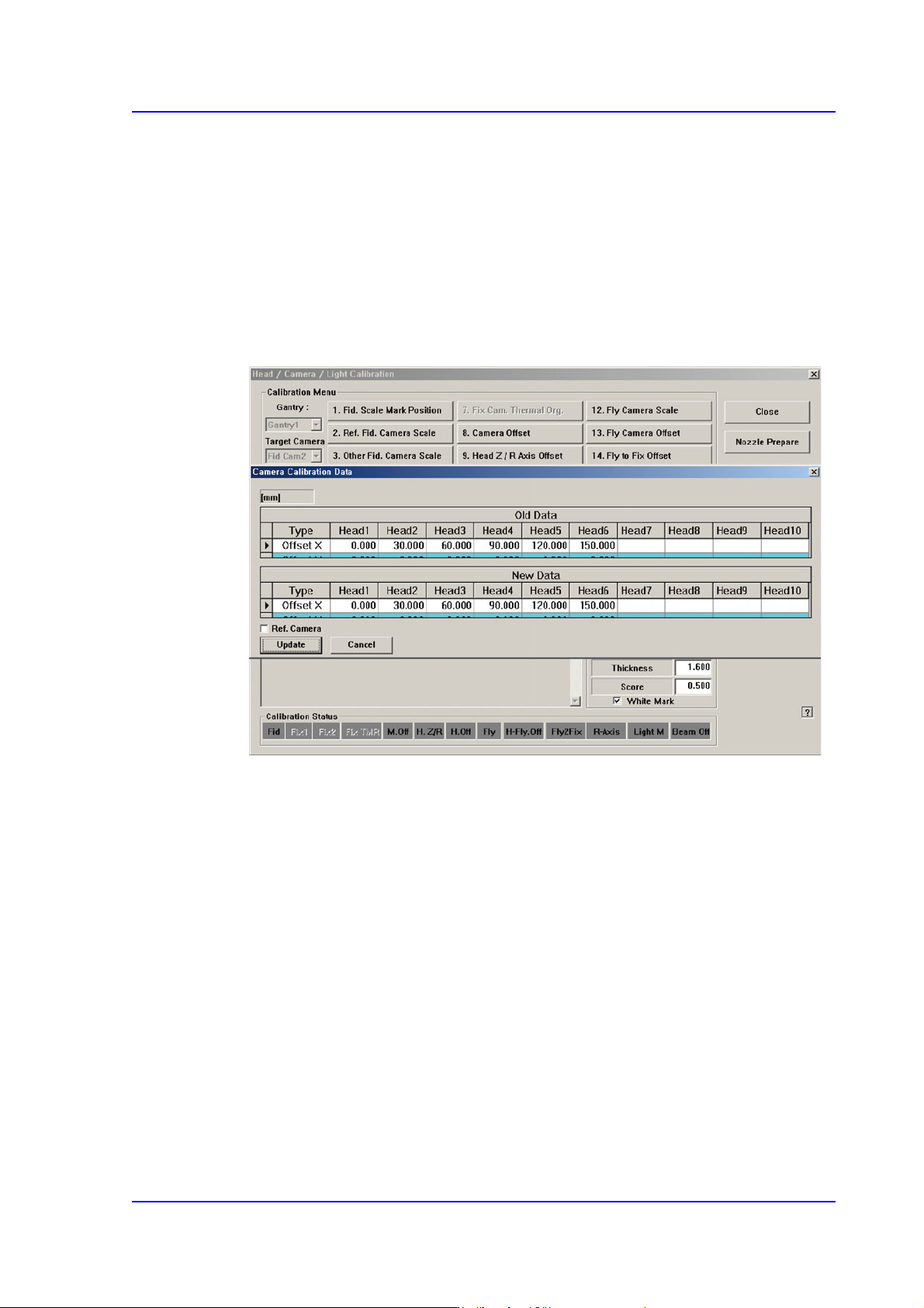
10. If the calibration procedure is completed for all heads normally, the result is displayed
as shown in the following figure. Click the <Update> button to apply the calibration
value.