SM482PLUS_Admin(Eng_Ver2.8).pdf - 第464页
15-10 Multi-Functional Placer SM482( L) PLUS Administrator’s Guide 15.2.2. <System Du mp> tab dialog Sets the data related to the dump bo x where picked components are dumped. Figure15.6 “System Dump” tab dialog …
15-9
System Setup
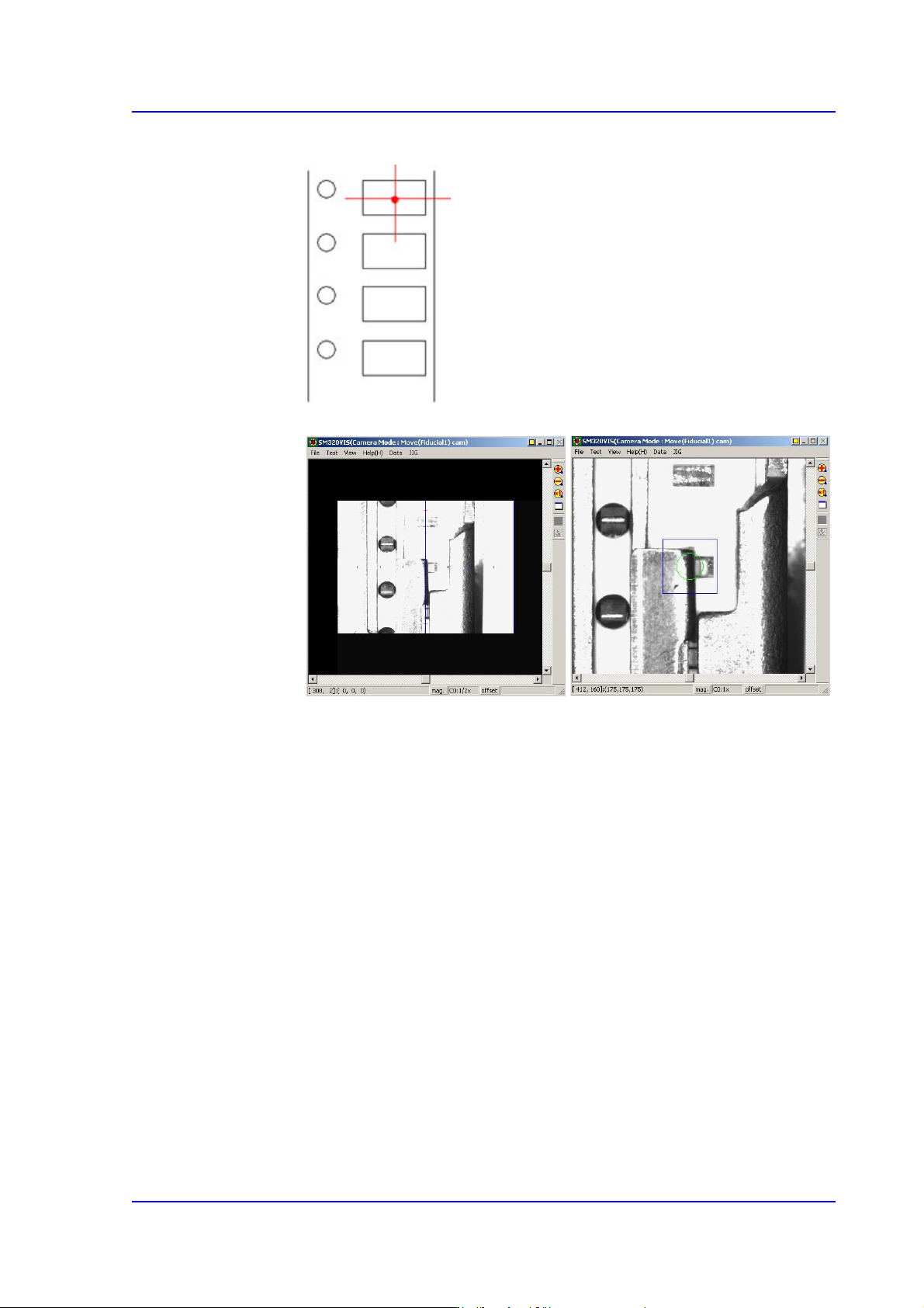
the center of the pocket, not on the center of the part.
5. Fit the center of the cross lines of ‘Fiducial Camera’ indicated in the
SMVision window to the pocket center, and input the value of the present
coordinates to the selected edit box by clicking on the <Get> button.
6. In the same way, install the feeder in the 21st slot of the rear feeder base, and
perform teaching.
<Height Offset> edit box
Set the Z value of the feeder base origin.
15-10
Multi-Functional Placer SM482(L) PLUS Administrator’s Guide
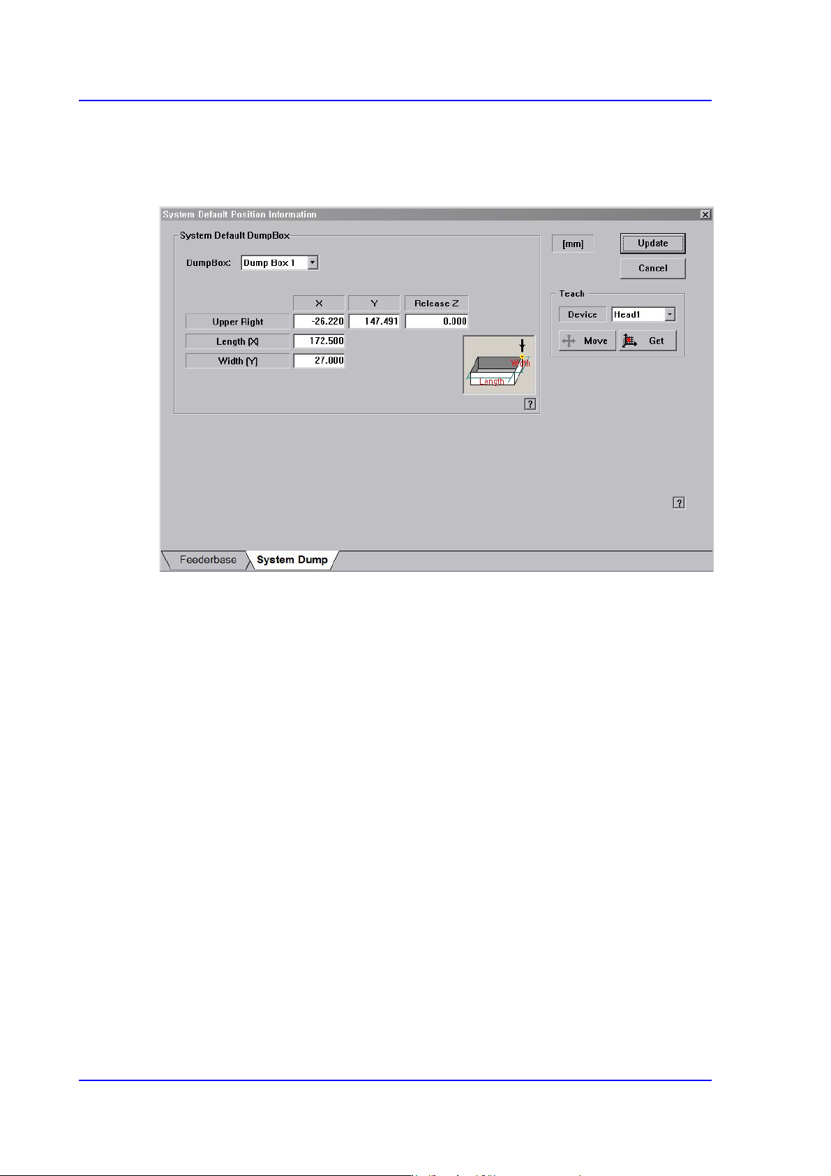
15.2.2. <System Dump> tab dialog
Sets the data related to the dump box where picked components are dumped.
Figure15.6 “System Dump” tab dialog
<System Default Dump Box> group
Inputs the position of the system dump box.
<Dump Box> combo box
Select the dump box to be set.
<Position - X, Y> edit box
Sets the X and Y positions of the head when dumping the components. Teach the
position (dump box center) at which parts are dumped.
<Release Z > edit box
Sets the Z axis of the head spindle when dumping parts.
<Length [X] > edit box
Inputs the dump box length.
<Width [Y] > edit box
Inputs the dump box height.
<Update> button
Transmits the set data to the equipment and closes the dialog box.
<Cancel> button
Ignores the set data and closes the dialog box.
15-11
System Setup
15.3. Peripherals [F6]
Configures the settings for dump box, tray feeder, flux device, and LCR checker.
Performs setup for the dump box, tray feeder and flux device.
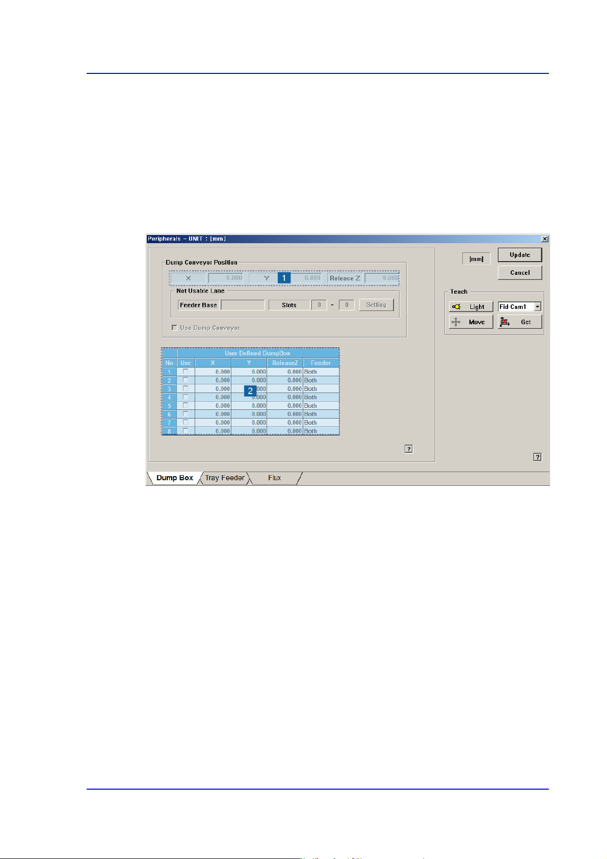
15.3.1. <Dump Box> tap dialog
Setup items related with the ‘Dump Conveyor’ and ‘Dump Box’ defined by the user.
Figure15.7 “Dump Box” tap dialog
1: Position
2: User Defined Dump box
<Dump Conveyor Position> group
Inputs the items to be set related to the dump conveyor. From the equipment which it
sees it is a function which it does not support.
‘Position’ group
X, Y: Enter the part dumping position on the dump conveyor by teaching the
X and Y coordinates.
Release Z: Enter the Z axis height when dumping the part.
<Not Usable Lane> group
From the equipment which it sees it is a function which it does not support.
<Setting> button
Clicked to set the feeder group that cannot be used due to the installation of
the dump conveyor.