SM482PLUS_Admin(Eng_Ver2.8).pdf - 第419页
14-47 Machine Calibration 5. The message “Move T o Center Position of [Fix1] Camera. T o Move, Click [Next]” appears in the message window . Click the <N ext> button to move the head assembly to the center of the f…
14-46
Multi-Functional Placer SM482(L) PLUS Administrator’s Guide
4. The message “Move To Center Position of Calibration Tool. To Move, Click
[Next].”appears. appears in the message window. Click the <Next> button to move the
head assembly to the calibration tool position on the ANC.
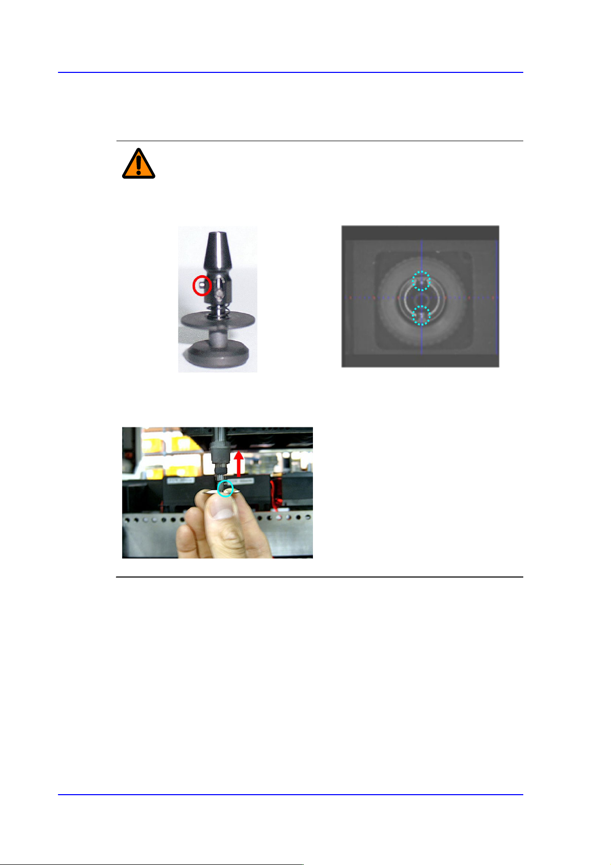
Caution Cautions to be taken when inserting the nozzle.
Insert the nozzle by referring to the following figure.
Direction Setup Pin of CNT20 nozzle
Direction Setup Groove of Nozzle
Holder
The CNT20 nozzle must be inserted
in the nozzle-holder so that the
direction-setup pin of the CNT20
nozzle is suitable for the direction-
setup groove of nozzle-holder.
Otherwise, an error may occur.
14-47
Machine Calibration
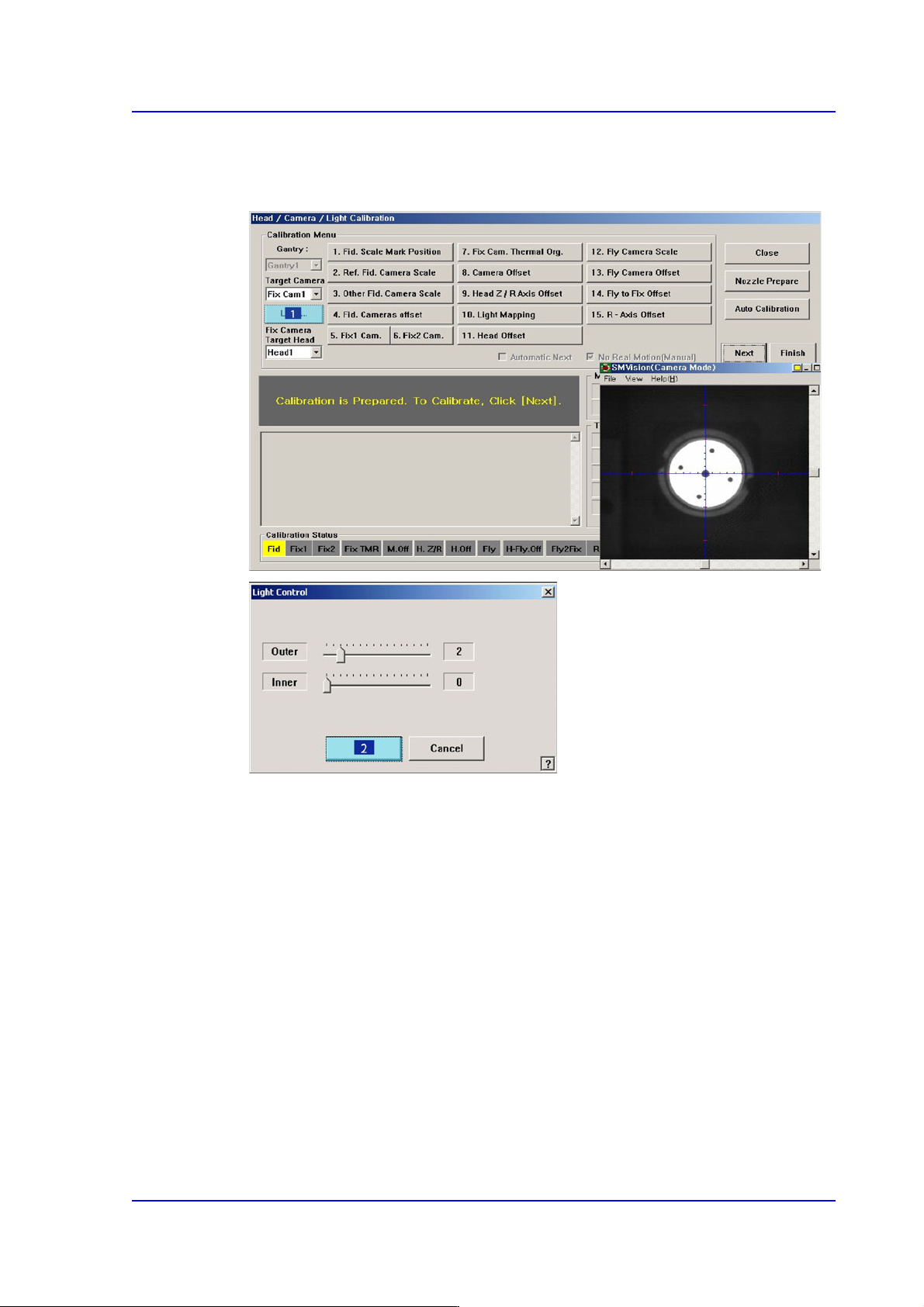
5. The message “Move To Center Position of [Fix1] Camera. To Move, Click [Next]”
appears in the message window. Click the <Next> button to move the head assembly
to the center of the fix-camera.
14-48
Multi-Functional Placer SM482(L) PLUS Administrator’s Guide
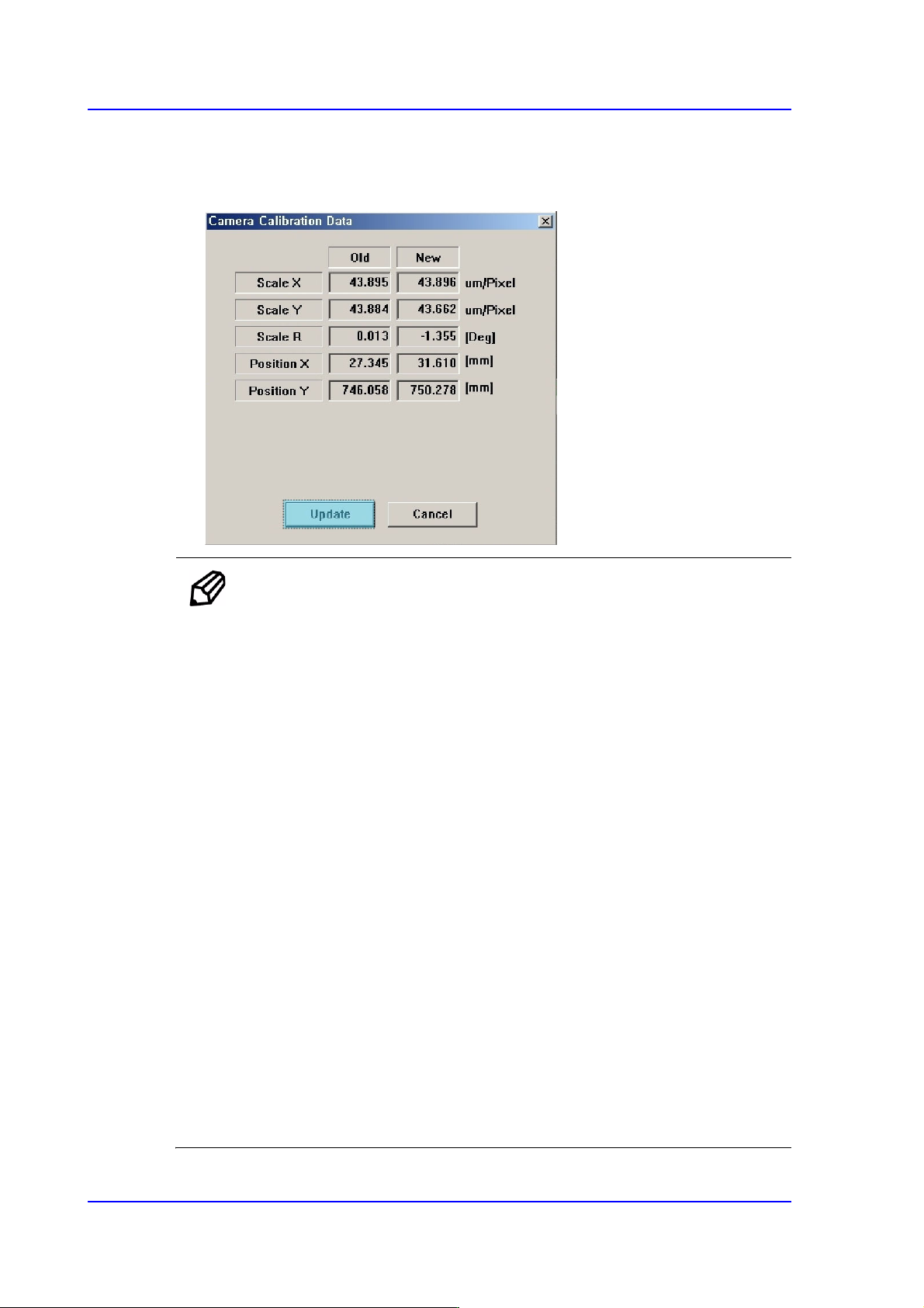
6. The calibration is performed automatically. If it is completed, the calibration result is
displayed as shown in the following figure. Click the <Update> button to apply the
new calibration value.
Memo The range of the reference values for the ‘fly-camera calibration’ is as
follows:.
Mega FOV 35
ScaleX:33.1~36.1 (μm/pixel)
ScaleY: 33.1~36.1 (μm/pixel)
R:-1~1(deg)
Mega FOV 45
ScaleX:42.7~45.7 (μm/pixel)
ScaleY: 42.7~45.7 (μm/pixel)
R:-1~1(deg)
FOV 35
ScaleX:70.9~74.9 (μm/pixel)
ScaleY: 70.9~74.9 (μm/pixel)
R:-1~1(deg)
FOV 45
ScaleX:91.8~95.8 (μm/pixel)
ScaleY: 91.8~95.8 (μm/pixel)
R:-1~1(deg)