SM482PLUS_Admin(Eng_Ver2.8).pdf - 第505页
15-51 System Setup The state of the equipment according to the de fault setup of the signal light is as follows: When the yellow lamp is turned on The equipment is in Idle or W ait state. It does not operate or it is w…

15-50
Multi-Functional Placer SM482(L) PLUS Administrator’s Guide
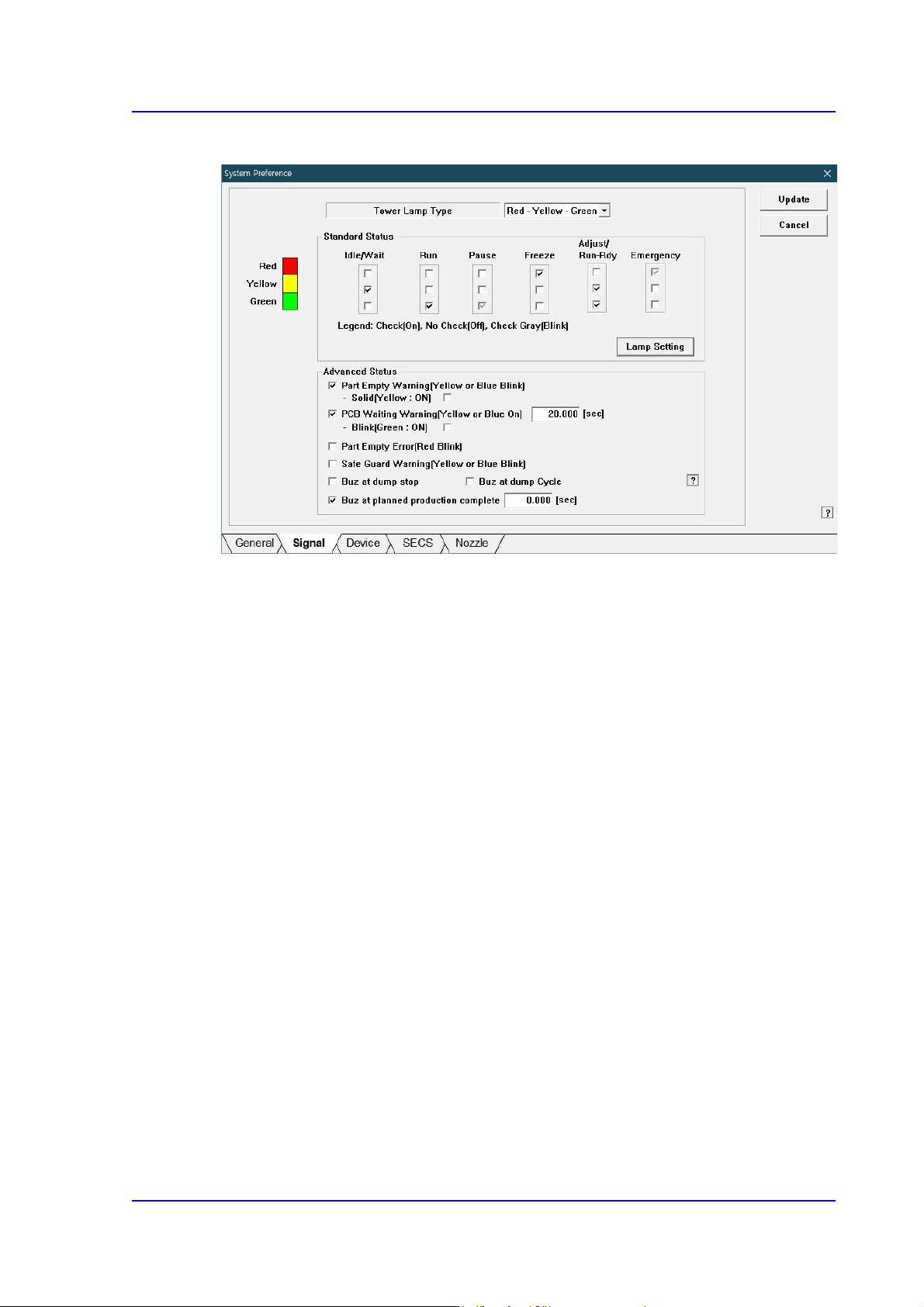
<Part Empty Error (Red Blink> check box
Red lamp blinks when ‘Part Empty’ error occurs.
<Safe Guard Warning (Yellow or Blue Blink> check box
Yellow lamp or blue lamp blinks when ‘Safe Guard Override’ function is released.
<Buz at dump stop> check box
If this check box is selected, the buzzer does not sound even though an error
occurs in the dump cycle. Since the buzzer does not sound, no work loss increases
significantly if an operator does not check the errors one by one.
<Buz at dump cycle> check box
If this check box is selected, the buzzer sounds only once even though parts are
dumped by several heads in one cycle.
<Buz at planned production complete> Check Box
If this check box is selected, a buzzer will generate a sound when the planned
production is complete.
<Update> button
Transmits the set option to the equipment and closes the dialog box.
<Cancel> Button
Ignores the changes in data and closes the dialog box.
15-51
System Setup
The state of the equipment according to the default setup of the signal light is as follows:
When the yellow lamp is turned on
The equipment is in Idle or Wait state. It does not operate or it is waiting during
operation.
When green lamp is turned on
The equipment is in Run state. It is in operation currently.
When green lamp is blinking
The equipment is in Pause state. It stops temporarily during operation.
When the red lamp is turned on
The equipment is in Freeze state. It remains stopped since an error occurred during
operation.
When yellow and green lamps are turned on simultaneously
The equipment is in Adjust or Run Dry state. It stops temporarily during operation
since certain measure needs to be taken.
When red lamp is blinking
The equipment is in Emergency state. It stops temporarily since an emergency error
occurred during operation.
15-52
Multi-Functional Placer SM482(L) PLUS Administrator’s Guide
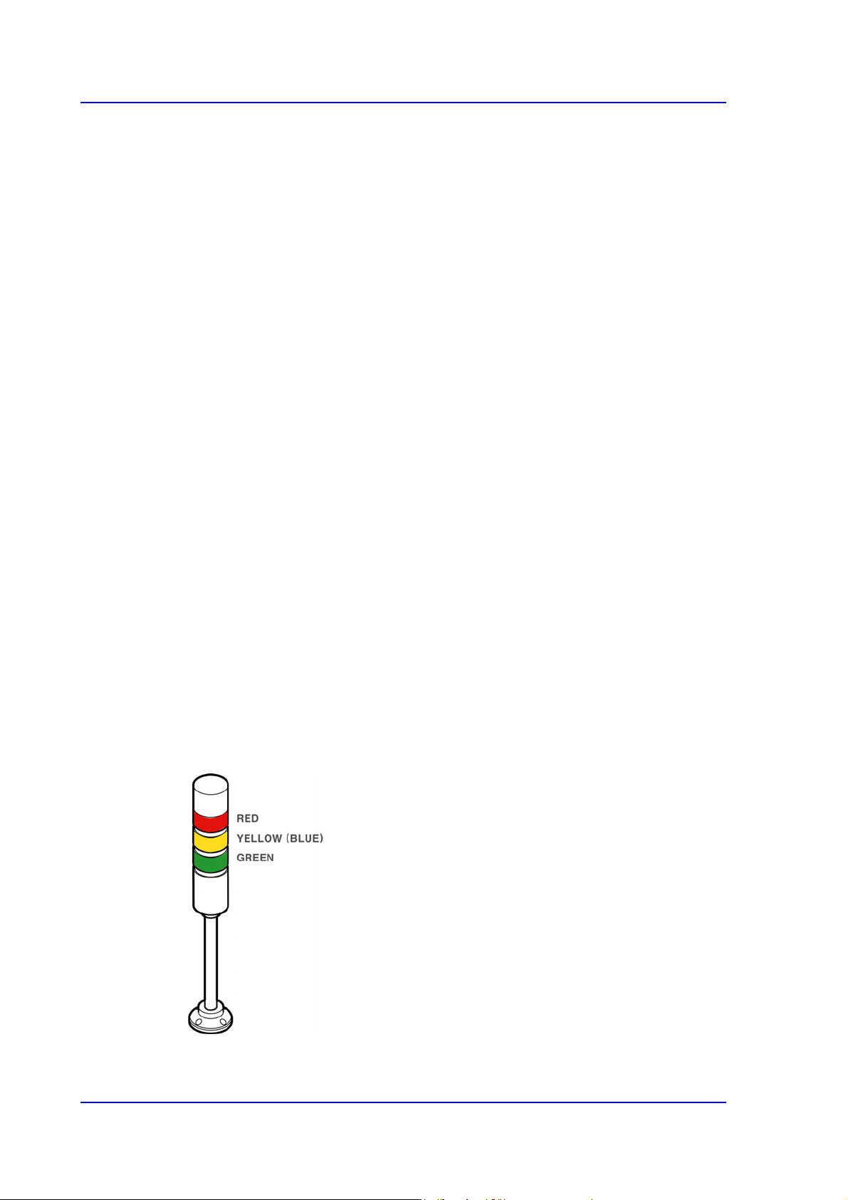
15.5.2.1. Standards for Lighting Signal Light
Indicates the operation status of the machine in the combination of lamps with three
colors. The user can check the machine status at a glance by looking at only the signal
light.
For more details about how to set the signal light, refer to “13.4.2. Lamp” in the
Administrator’s Guide.
Lighting of a red lamp
Indicates the stop status through self-diagnosis of the system. Warning sounds ring
continuously and messages are indicated as the red lamp is lighted.
Flashing of a red lamp
Indicates either the pressing of the ‘EMG’ switch or the emergency stop status through
self-diagnosis of the system. Warning sounds ring continuously and messages are
indicated as the red lamp is flashed.
Lighting of a yellow lamp
Indicates the standby status of operation.
Flashing of a yellow lamp
Indicates either component shortage in the tray feeder or adsorption error. Warning
sounds ring continuously and messages are indicated as the yellow (or blue) lamp is
flashed.
Lighting of a green lamp
Indicates that this machine is currently being operated automatically.
Flashing of a green lamp
Indicates temporary stop status. Automatic operation can be resumed by pressing the
START button.
Figure15.18 Signal Light