SM482PLUS_Admin(Eng_Ver2.8).pdf - 第288页
8-36 Multi-Functional Placer SM482( L) PLUS Administrator’s Guide <Current Pocket> group <X>: Set the pocket number of the tray to move to or pick up from in X direction. <Y>: Set the pocket number of…
8-35
Feeder Setup
<Pick> button
Picks up the part from the pocket of the currently selected pallet. At this time, the head
to pick up the part must be selected in advance.
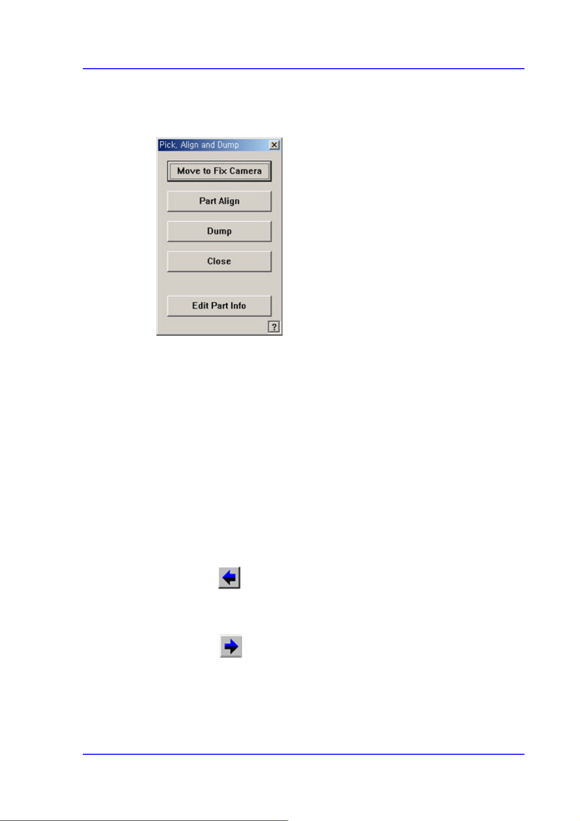
<Move to Fix Camera> button
It is activated only when the corresponding component is aligned by the vision
camera and the alignment camera is the fix camera. When this Button is clicked
on, the head block is moved to the fix camera.
<Part Align> button
Executes alignment of the corresponding component.
<Dump> button
Dumps the corresponding component to the specified dump box.
<Close> button
Closes the dialog box.
<Pocket Move> button
Moves the selected device to the pocket number set in <Current Pocket>.
<Move Prev> button
Moves the selected device to the pocket number previous to the number set in
<Current Pocket>.
<Move Next> button
Moves the selected device to the pocket number next to the number set in <Current
Pocket>.
8-36
Multi-Functional Placer SM482(L) PLUS Administrator’s Guide
<Current Pocket> group
<X>: Set the pocket number of the tray to move to or pick up from in X direction.
<Y>: Set the pocket number of the tray to move to or pick up from in Y direction.
<Install to Feeder Base> group
Displays the feeder base unit and slot number when the tray unit is set to the feeder
base.
<Feeder Base>
Designates the feeder base where the stick feeder is to be installed.
0: Not installed on any feeder base.
1: Installed on Feeder Base1(Front Feeder Base).
2: Installed on Feeder Base2(Rear Feeder Base).
<Slot No.>
Displays the number of the feeder base slot in which the corresponding tray unit is
installed currently. The numbers displayed are as follows.
0: Not installed in any slot.
1 - 52: Installed in the corresponding number slot.
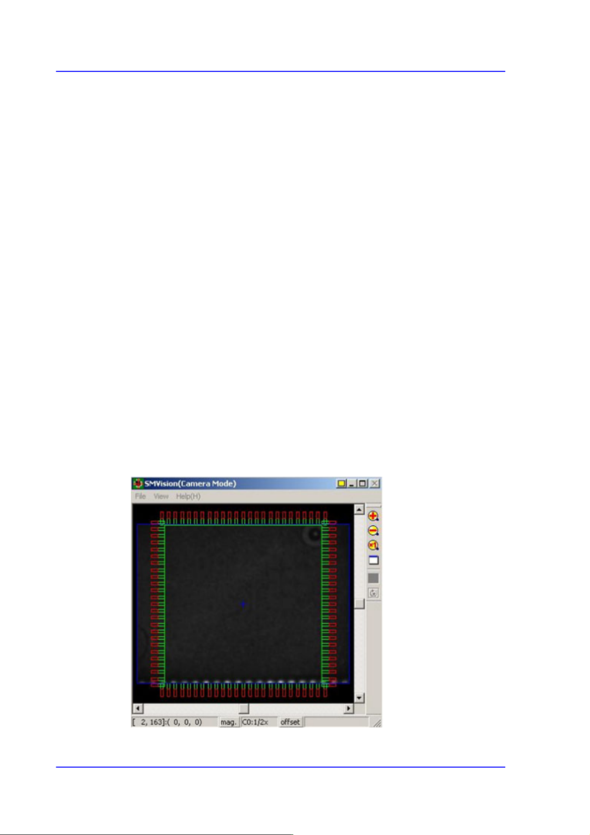
<Part Outline> check box
If this check box is selected, when the fiducial camera is moved to the position of the
corresponding feeder to check the pickup position, the outline image that considers the
angle at which the corresponding part is picked up is displayed on the SMVision
window.
9-1
Step Programming
Chapter9. Step Programming
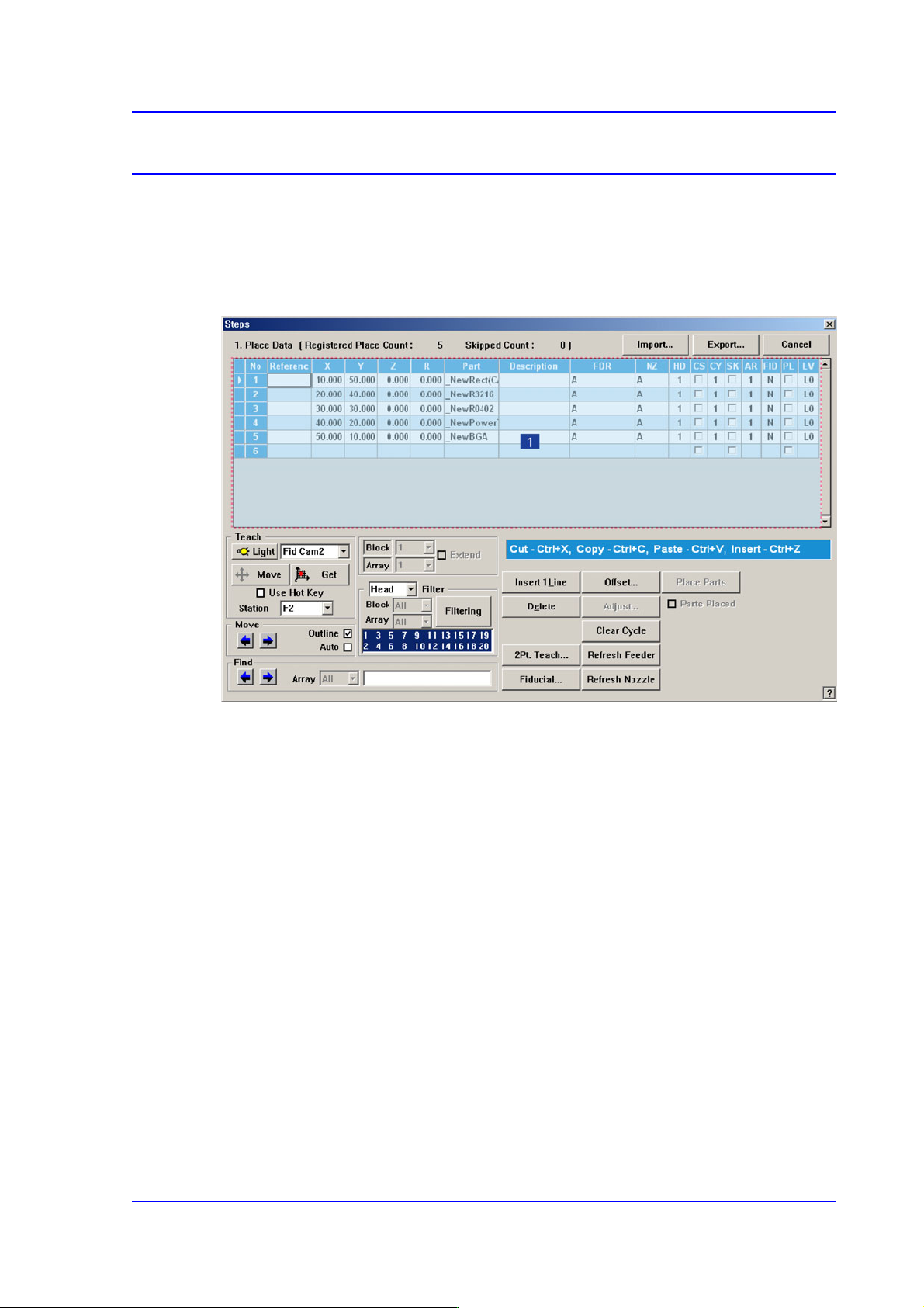
The ‘Step’ submenu edits data on PCB placement points, component fiducial marks,
components to be placed, component supplying feeders, and nozzles to pick up
components.
Figure9.1 “Steps” dialog box
1: Grid
‘Grid’ group
Set the edit data related to placement.
<No> column
Refers to the number of the placement point.
<Reference> column
Set the reference name of the placement point. In general, enter the value of R1,
R2, C1, and C2 on the PCB (up to 8 characters).
<X> column
Set the X position of the placement point.
<Y> column
Set the Y position of the placement point.
<Z> column
Set the Z position of the placement point.