SM482PLUS_Admin(Eng_Ver2.8).pdf - 第260页
8-8 Multi-Functional Placer SM482( L) PLUS Administrator’s Guide installed in the feeder base slot properly , th is function is used to automatically adjust the pickup point . In the case of the Chip-Rect part that is fe…
8-7
Feeder Setup
Combo Box
Used for selecting the object to move to the designated coordinates by rotating the
XY axis driving motor or to select the object for which the present coordinates is
searching. Selectable objects are as follows;
Fid Cam: Selects the fiducial camera of the head.
Head 1 ~ Head 6: Selects the Head #1~Head #6
Beam1: Selects the Height Sensor.
<Move> button
Move the object selected in the Combo Box to the position of the assigned
coordinates. Before executing <Move> button, the cell in the grid (Coordinates for
pickup point of tape feeder) corresponding to the desired position must be clicked
on.
<Get> button
Obtain coordinates for XY axis with reference to the object selected in the Combo
Box. At this time, Before executing <Get> button, the cell in the grid (Coordinates
for pickup point of tape feeder) corresponding to the desired position must be
clicked on.
<Slot Move> button
Selects whether to move the selected device by a slot or by the slot where the tape
feeder is installed. Every time this Button is clicked, “Slot Move” and “Feeder
Move” are set in turn.
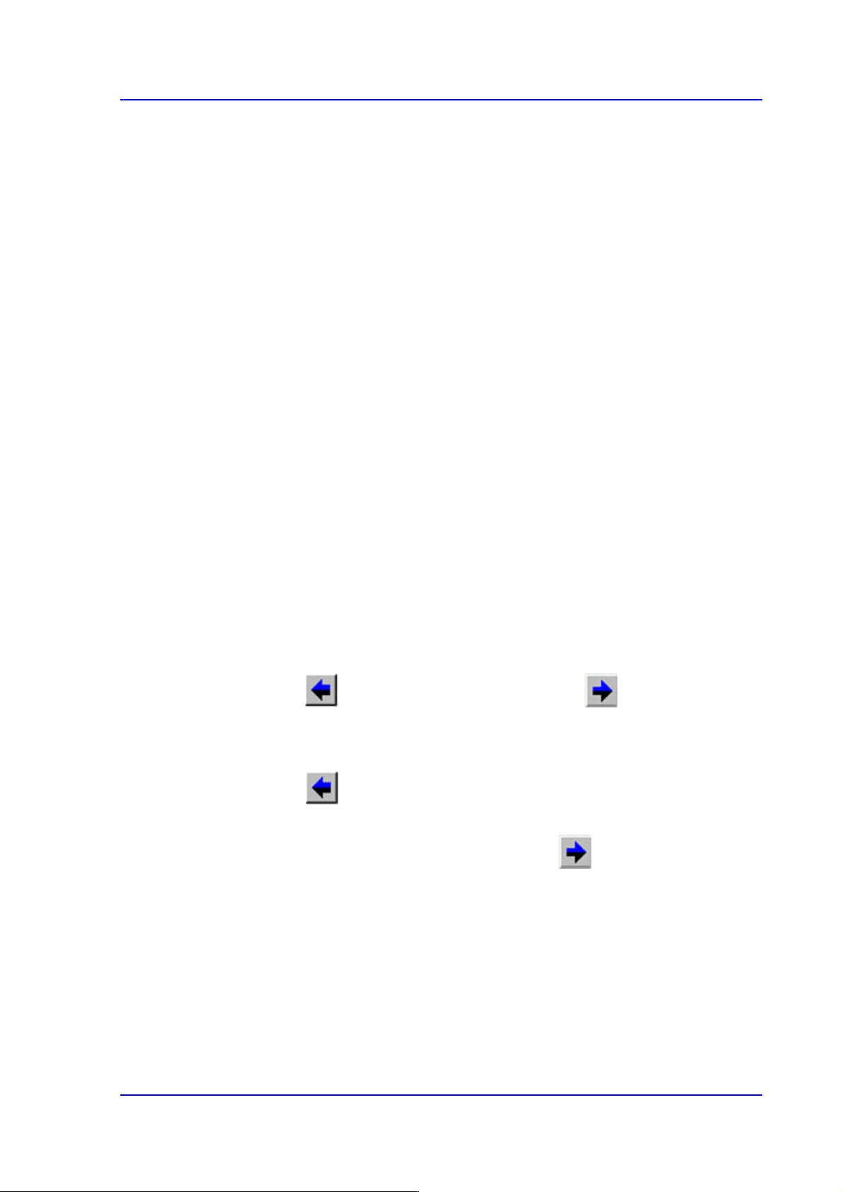
For Slot Move
The button selects the previous slot and the button selects the next
slot.
For Feeder Move
The button selects the slot where the tape feeder is installed among the
slots previous to the slot where the currently selected feeder is installed (in the
order from the lower to higher number). The button selects the slot
where the tape feeder is installed among the slots next to the slot where the
currently selected feeder is installed (in the order from the higher to lower
number)
<Pocket Teach> button
Used to perform the ‘Pocket Teach’ function manually for the tape feeder selected
from the “Feeders” dialog box.
When the pickup point is different from the pickup point set by the system due to the
problem of the corresponding feeder even though certain feeder base has been

8-8
Multi-Functional Placer SM482(L) PLUS Administrator’s Guide
installed in the feeder base slot properly, this function is used to automatically adjust
the pickup point.
In the case of the Chip-Rect part that is fed by the tape feeder, the part pickup can be
done more accurately if the Pocket Teach function is used.
If a pickup error occurs during default operation, the machine tries to pick up the part
as many times as the set number of times of retry for the corresponding part. If the
number of times of the retry exceeds the last count, the machine creates an error and
stops operation.
However, in the case of the part that is fed by the tape feeder before the number of
times the retry exceeds the last count, find the correct pickup point by using the Pocket
Teach function and calibrate the pickup position before performing pickup.
The Pocket Teach recognizes the pockets or sprocket holes of the tape being supplied,
and calibrates current pickup position matches with the center of the pocket.
Teaching the Pocket Teach will reflect its result in the <PT> column in the <Grid>
group.
(ON-S: Successful, ON-F:Failed)
If the setup is performed so that the ‘Pocket Teach’ function can be executed during
automatic operation, this function is not applied when the <PT> column is OFF or
ON-F in the <Grid> group in the “Feeder Registration” dialog box.
Caution If the corresponding function is used while performing
placement, the pickup success rate of the corresponding
feeder can be improved. However, it takes time to perform
pocket teaching, and simultaneous pickup may not be
performed since the pickup point coordinate is
compensated.
Memo Performing pocket teaching will automatically reflect the offset
information obtained during pocket teaching and automatically
correct the home offset of the tape feeder. However, the corrected
offset value will be applied during the next feeding.
If the distance between the position recognized by the vision
system and the logical origin exceeds 0.2mm, the feeder ignores
the offset value.
A motor driven feeder using parts other than 1005/0603 parts
does not use the home offset adjustment function.
8-9
Feeder Setup
<Pocket Teach All> button
Performs the ‘Pocket Teach’ function repeatedly for all tape feeders with the <PT>
column being set to ON or ON-S in the <Grid> group in the “Feeders” dialog box
among the tape feeders installed in the corresponding feeder base.
<Pick> button
Performs pickup of the parts for the tape feeder presently selected in the “Feeder
Base” dialog box. A device (Head to pickup) must be selected first. It is displayed
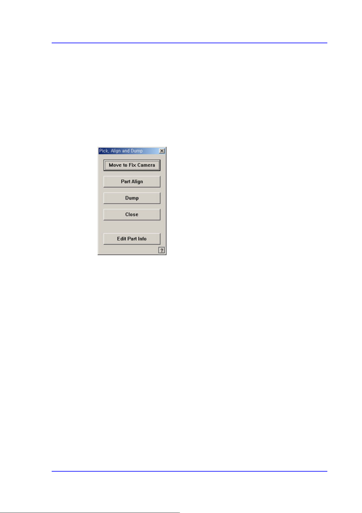
alternately every time the Pick and Dump are clicked. When the pick-up is successful,
the following dialog box is displayed.
<Move to Fix Camera> button
It is activated only when the corresponding component is aligned by the vision
camera and the align camera is the fix camera. When this Button is clicked on,
Moves the selected object in the <Device> combo box of the <Teach> area to the
position of the fix camera.
<Part Align> button
Executes alignment of the corresponding component.
<Dump> button
Dumps the corresponding component to the dump box.
<Close> button
Closes the dialog box.
<Edit Part Info> button
Closes the dialog box.
<2Pt. Teach…> button
When teaching the tape feeder pick-up position, This function is used when it is
difficult to teach the part center because the entire part is not viewed in the screen. It
teaches the part center by teaching 2 points at the edges that face with each other
diagonally.When this Button is clicked on, the following dialog box is displayed.