Administrator’s Guide(CP45FV) Eng.pdf - 第105页
Part Registration 7-21 7.2.5. T rimmer component data setting Set align data for T rimmer com ponents. Figur e 7-14. “ Align T ype = V ision, Package Gr oup = T rimmer ” dialog box <Camera No.> …

Samsung Component Placer CP45FV Series Administrator’s Guide
<Down Lead L> edit box
Set the length of lower lead in Y direction.
<Down Lead P> edit box
Set the pitch between lower leads.
Please refer to “7.2.1.1 Common Align Data (Page 7-9)” for more information.
<Option> group
Set align option data.
<Algorithm White Body> check box
Check it if the color of the component body is “White Body”.
<Algorithm Heat> check box
Check it if a radiator is attached to the component body.
Please refer to “7.2.1.1 Common Align Data (Page 7-9)” for more information.
<Outline> button
Displays the outline of the component on the vision monitor by using the set align
data.
<Move…> button
Performs component pickups or moves to the fix camera. Please refer to “7.2.1.1
Common Align Data (Page 7-9)” for more information.
<Test> button
Tests component recognition by using the set align data. Please refer to “7.2.1.1
Common Align Data (Page 7-9)” for more information.
<Image Capture> button
Helps to specify the optimum lighting value. The lighting is gradually changed
automatically and the images are saved. The user can check the best image and
identify the optimum lighting value.
Please refer to “7.2.1.1 Common Align Data (Page 7-9)” for more information.
7-20
Part Registration
7-21
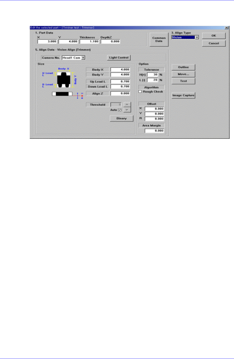
7.2.5. Trimmer component data setting
Set align data for Trimmer components.
Figure 7-14. “Align Type = Vision, Package Group = Trimmer” dialog box
<Camera No.> combo box
Select the camera to recognize the component. Please refer to “7.2.1.1 Common Align
Data (Page 7-9)” for more information.
<Light Control> button
Set the light for the camera to recognize the component. Please refer to “7.2.1.1
Common Align Data (Page 7-9)” for more information.
<Size> group
Set the align size
<Body X> edit box
Set the component size in X direction.
<Body Y> edit box
Set the component size in Y direction.
<Up Lead L> edit box
Set the length of the upper lead in Y direction.
<Down Lead L> edit box
Set the length of the lower lead in Y direction.
Please refer to “7.2.1.1 Common Align Data (Page 7-9)” for more information.
<Option> group
Set the align option data.
<Algorithm Rough Check> check box
Check it to recognize roughly for component recognition.
Please refer to “7.2.1.1 Common Align Data (Page 7-9)” for more information.
<Outline> button
Displays the outline of the component on the vision monitor by using the set align
Samsung Component Placer CP45FV Series Administrator’s Guide
data.
<Move…> button
Performs component pickups or moves to the stage camera. Please refer to “7.2.1.1
Common Align Data (Page 7-9)” for more information.
<Test> button
Tests component recognition by using the set align data. Please refer to “7.2.1.1
Common Align Data (Page 7-9)” for more information.
<Image Capture> button
Helps to specify the optimum lighting value. The lighting is gradually changed
automatically and the images are saved. The user can check the best image and
identify the optimum lighting value.
Please refer to “7.2.1.1 Common Align Data (Page 7-9)” for more information.
7.2.6. Hemt component data setting
Set the align data for Hemt components.
Please refer to “Setting User IC component data”.
7.3. IC component data setting
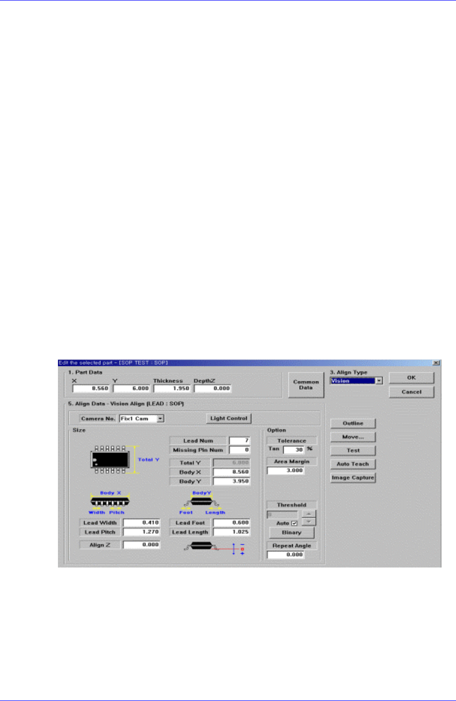
7.3.1. SOP component data setting
Set the align data for SOP components.
Figure 7-15. “Align Type = Vision, Package Group = SOP” dialog box
<Camera No.> combo box
Select the camera to recognize the component. Please refer to “7.2.1.1 Common Align
Data (Page 7-9)” for more information.
<Light Control> button
Select the light for the camera to recognize the component. Please refer to “7.2.1.1
Common Align Data (Page 7-9)” for more information.
7-22