Administrator’s Guide(CP45FV) Eng.pdf - 第119页
Part Registration 7-35 All Body: Applied to various types of components, but it takes long to process. Applied to non IC types or hard to recognize components. Odd with No Lead: Applied to odd type components without lea…

Samsung Component Placer CP45FV Series Administrator’s Guide
Select the camera to recognize the component. Please refer to “7.2.1.1 Common Align
Data (Page 7-9)” for more information.
<Light Control> button
Set the light for the camera to recognize the component. Please refer to “7.2.1.1
Common Align Data (Page 7-9)” for more information.
<Size & Etc> group
Set the align size.
<Body X Typical> edit box
Set the size of component body in X direction.
<Body X Max> edit box
Set the maximum size of component body in X direction.
<Body X Min> edit box
Set the minimum size of component body in X direction.
<Body Y Typical> edit box
Set the size of component body in Y direction.
<Body Y Max> edit box
Set the maximum size of component body in Y direction.
<Body Y Min> edit box
Set the minimum size of component body in Y direction.
<Align Z> edit box
Set the height for recognition. Based on the component surface, if the top is to be
recognized, set - value and if the bottom is to be recognized, set + value.
<Lead Parameter & Group> button
Set the lead parameter and lead group. Please refer to <7.4.1 Lead Parameter>,
<7.4.2 Lead Group>.
<Option> group
Set the align option data.
<Area Margin> edit box
Set the limit for the image to be off the center of the screen when the component
is recognized. For example, if this value is 5mm, then the image of the
component should be within 5mm of the center of the screen.
<Lead Type> combo box
Select the lead type. Available lead types are as follows.
Gull-Wing: Leads protrude outward as QFP.
J-Lead: Leads roll inward as PLCC.
<Algorithm> combo box
Select the algorithm to recognize the component. Available algorithms are as
follows.
Black Body: Method to process IC types fast. In general, applied to IC types.
7-34
Part Registration
7-35
All Body: Applied to various types of components, but it takes long to process.
Applied to non IC types or hard to recognize components.
Odd with No Lead: Applied to odd type components without leads.
Odd with Lead: Applied to odd type components with leads.
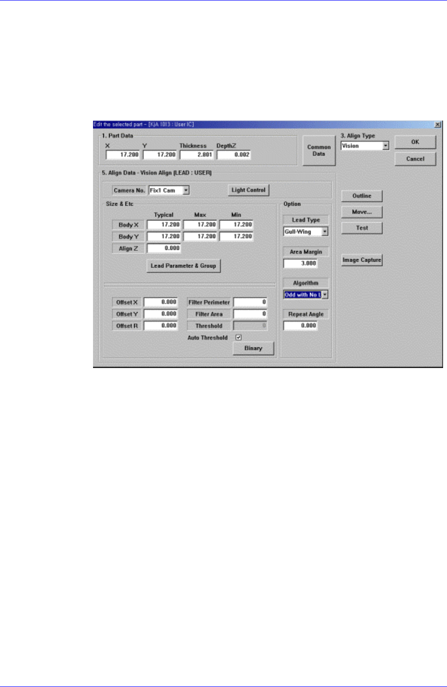
When <Algorithm> is “Odd with No Lead” or “Odd with Lead”, the following
dialog box is displayed.
Figure 7-24. “
A
lign Type = Vision, Package Group = User IC, Algorithm = Odd with
Lead” dialog box
<Offset X> edit box
Set the offset value between the component centroid and the actual
component center in X direction.
<Offset Y> edit box
Set the offset value between the component centroid and the actual
component center in Y direction.
<Offset R> edit box
Set the offset value between the angle of the main axis of the component and
the actual angle.
<Filter Perimeter> edit box
Set the value to remove noise in the component vision image. If the
perimeter of the object in the image is smaller than this value, it is processed
as noise.
<Filter Area> edit
Set the value to remove noise in the component vision image. If the area of
the object in the image is smaller than this value, it is processed as noise.
<Threshold> edit box
When there is a pre-treatment process for component recognition and the

Samsung Component Placer CP45FV Series Administrator’s Guide
gray level image is converted into binary, it is the value used as the criteria to
determine black and white.
The value range is 0 – 255(0: black, 255: white), and this value serves to
differentiate the component from the background. When the set value is 0,
the value is set automatically during component recognition.
<Auto Threshold> check box
Check it to set the <Threshold> value automatically.
<Binary> button
Displays the binary image of the component on the Vision Monitor screen.
<Repeat Angle> edit box
In the case of the work needed for high precision, this re-recognizes and pick-up
and placement of the component by performing correction according to the
vision recognition result. For example, if o.i is inputted for the repeat angle, it
corrects the angle after vision recognition and re-recognizes it. If the result of re-
recognition is greater than 0.1 it recognizes the angle after correcting the angle. It
repeats this until the result of the recognition become less than 0.1. When the
value becomes 0.1, it pick and place the component (it tries recognition up to 4
times)
<Outline> button
Displays the outline of the component on the vision monitor by using the set align
data.
<Move…> button
Performs component pickups or moves to the fix camera. Please refer to “7.2.1.1
Common Align Data (Page 7-9)” for more information.
<Test> button
Performs the component recognition test by using the set align data. Please refer to
“7.2.1.1 Common Align Data (Page 7-9)” for more information.
<Image Capture> button
Helps to specify the optimum lighting value. The lighting is gradually changed
automatically and the images are saved. The user can check the best image and
identify the optimum lighting value.
Please refer to “7.2.1.1 Common Align Data (Page 7-9)” for more information.
7-36