Administrator’s Guide(CP45FV) Eng.pdf - 第223页
Placement T est 14-9 After correcting the X and Y coordinates us ing the teaching box, select the feeder to be corrected from the following dialog box and then click the <Get> button to reflect the changed coordina…
Samsung Component Placer CP45FV Administrator’s Guide
14.3.3. Component Pickup Error
This refers to the error occurred while the component is picked up from the feeder.
Causes of the component pickup error includes component feed defect, pickup point error,
nozzle defect and vacuum defect.
Component feed defect
Occurs when there is no component in the feeder or when the components are not fed
smoothly due to the defective operation of the feeder. Check the feeder by performing
component feeding several times. If there is any problem, replace it with another
feeder.
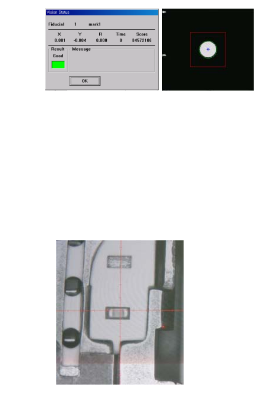
Pickup Position Error
Occurs when the coordinate of the pickup position is out of the component pickup
area as in the following cases: 1) The X and Y coordinates of the pickup position are
out of the area where the component can be picked up; 2) The component pickup
height is different from the position of the actual component pickup height.
When X and Y coordinates of the pickup position are out of the area where the
component can be picked up
The above figure shows that the X and Y coordinates of the pickup position are
out of the area where the component can be picked up.
14-8

Placement Test
14-9
After correcting the X and Y coordinates using the teaching box, select the feeder
to be corrected from the following dialog box and then click the <Get> button to
reflect the changed coordinates.
Samsung Component Placer CP45FV Administrator’s Guide
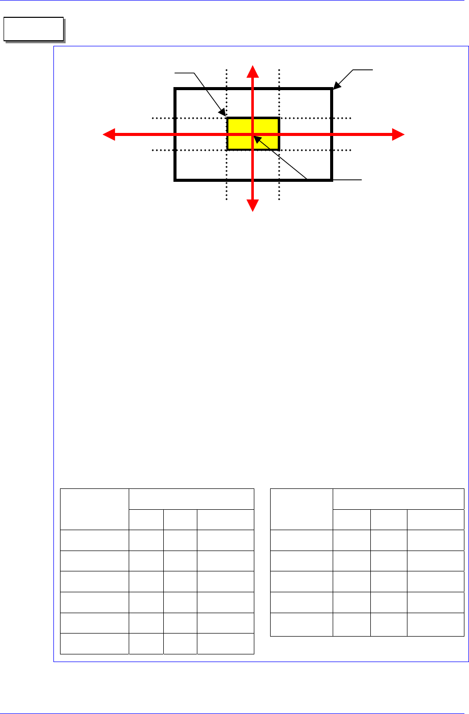
1. On 1/3 area of component pocket
First, check if the feeder is normally installed on the feeder base. If a feeder is installed
while a chip is stuck on the feeder base, the pickups position will be deviated to that
extent.
It is all right to use the feeder position (or pickups position) without changing it if the
crossing point of the red arrows on the vision monitor is within 1/3 area of component
pocket. When the feeder is installed normally, but the pickups position and the crossing
point of the red arrows are on the outside of 1/3 area of component pocket, the feeder is
considered to be abnormally installed. In this case, change the feeder, teach again, and
install it.
2. Component pickups point
Do not change the component pickups position if possible. Use the original coordinate
and it is recommended to use a value between 0.00 and 0.50 for Z axis coordinate.
3. Data value for normal chip components (1005 ~ 3216)
The machine speed and time delay when registering regular chip components are
as follows. The data differs according to the chip size. As chip components 0603
and 1005 are tiny, it is best to place them under a condition different from the one
for other chip components. However, they are not absolute. Rather, it is best to use a
value in these ranges to avoid putting strain on the machine.
Component pocket
area
Memo
1/3
2/3
1/3
2/3
1/3 area of component
pocket
Crossing point of the red
arrows on the vision
monitor
Speed
Item
0603 1005 1608~3216
XY 1 1 1
R 1 1 1
Z Pick down 1 3 1
Z Pick up 3 2 1
Z Place down 1 1 1
Z Place up 1 1 1
Time Delay
Item
0603 1005 1608~3216
Pick up 0 20 30
Place 25 25 10
Vacuum off 0 0 0
Dump 100 100 100
Vacuum vac.
off
0 0 0
When the component pickup height is different
The error occurs when the pickup height at which the machine turns on the
14-10