Administrator’s Guide(CP45FV) Eng.pdf - 第249页
Machine Calibration 15-1 1 Outer Lighting Device Bottom N ozzle wing 6. Close the Manual Tools dialog box. 7. At this time, appl y the Axis Z value in the “ Position ” dialog box as the Z value of the Check Position. Noz…
Samsung Component Placer CP45FV Administrator’s Guide
fourth (third) scale of the vision monitor.
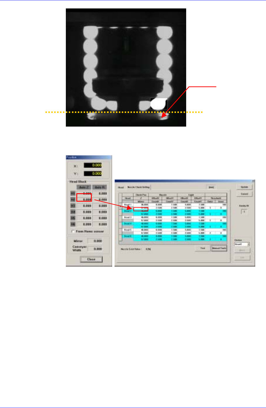
When using the FOV
15mm Fly Camera
When using the FOV 15mm Fly Camera, align the LED bottom line with the
fourth (third) scale of the vision monitor.
6. Close the Manual Tools dialog box.
7. At this time, apply the Mirror value in the “Position” dialog box as the Mirror
value of the Check Position.
Z-axis Height Teaching (Head Z Teaching)
The default value is 46 for the CP45FV and 48 for the CP45FV NEO.
1. Select the Current Position in the View menu and execute the “Position”
dialog box.
2. Click the <Manual Tools> button in the Nozzle Check Setting Tab dialog
box and execute the “Manual Control” dialog box.
3. Select the Z in the <Axis> combo box of the Axis Tab dialog box.
4. Select the Camera in the Camera Tab dialog box, which corresponds to the
head for which whether the nozzle is mounted is checked.
5. Move the Z-axis so that the nozzle wing surface contacts the bottom of the
outer lighting device.
15-10
Machine Calibration
15-11
Outer Lighting Device
Bottom
Nozzle wing
6. Close the Manual Tools dialog box.
7. At this time, apply the Axis Z value in the “Position” dialog box as the Z
value of the Check Position.
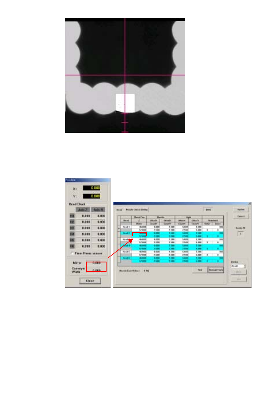
Nozzle Offset Teaching
1. If the Offset X and Y cells are clicked, the <Test> button is activated. At this
time click the <Test> button.
2. The test area is displayed as a box on the vision screen. Set the Offset X and
Offset Y values so that the test box is placed at the center of the lower LED.
The coordinate system for setting X and Y values is the Right-Down
coordinate system.
Samsung Component Placer CP45FV Administrator’s Guide
The vision screen after the
<Test> button is clicked
Nozzle Count Teaching
1. If the Offset X and Y cells are clicked, the <Test> button is activated. At this
time click the <Test> button.
2. The test area is displayed as a box on the vision screen. Set the Count X
(Width) and Count Y (Height) of the test box so that the Pixel Count
Percentage becomes greater than 70% when clicking the test box. The box
size changes based on the previously set Offset X and Y values.
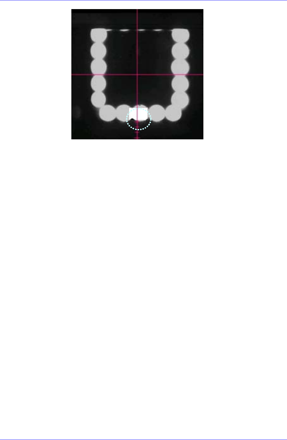
Light Offset Teaching
This is performed in preparation for a case in which the light is not turned on
when the Pixel Count Percentage value below 30 is obtained, which means that a
nozzle is mounted. Set this area after mounting the largest nozzle.
The only difference between Nozzle Offset Teaching and Nozzle Count
Teaching is the position of the test box.
1. If the Offset X and Y cells are clicked, the <Test> button is activated. At this
time click the <Test> button.
2. When clicking the <Test> button, the test box is the bright area (LED) on the
bottom right. Set the Pixel Count Percentage to a value greater than 70% for
testing.
15-12