Administrator’s Guide(CP45FV) Eng.pdf - 第216页
Samsung Component Placer CP45FV Administrator ’ s Guide Click the <Shutter On/Off> in the ANC dial og box t o open the shutter and arrange the nozzle manually . Wa r n i n g Operating the shutter while a finger is …
Placement Test
Chapter 14. Placement Test
14-1
The placement test must be performed to check if the PCB file setup and machine setup
have been performed properly. Incorrect setup may be corrected through the placement
test.
14.1. Preparation for Placement Test
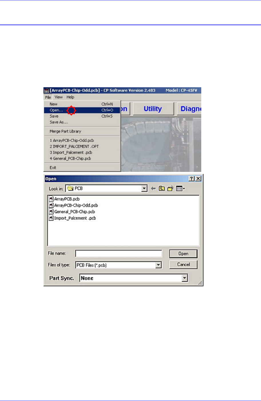
1. Load the prepared PCB file to the MMI (Application Program). (File opening)
2. Once the PCB file is selected and loaded, the following message dialog box may be
displayed. This is displayed when the current machine setup is different from that of
the PCB file to be loaded.
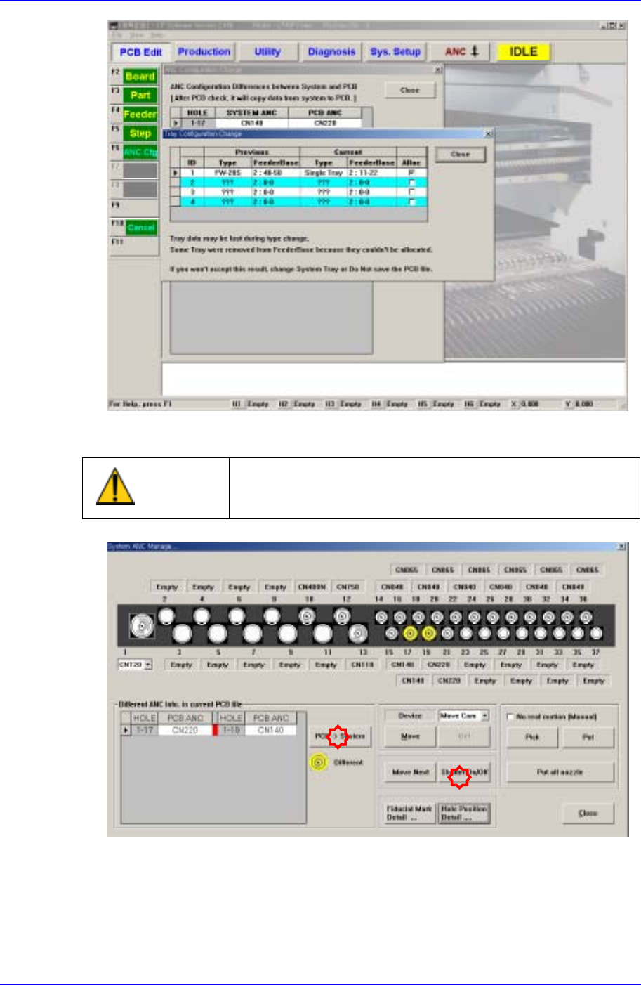
The “Tray Configuration Change” screen indicates that the type of the tray feeder that
is setup in the actual machine (or that is setup in the PCB file) is different from the
type of the tray feeder that is setup by the PCB file to be loaded.
The “ANC Configuration Change” screen indicates that the nozzle arrangement in the
ANC that is setup in the actual machine (or that is setup in the last PCB file loaded
previously) is different from the nozzle arrangement in the ANC that is setup by the
PCB file to be loaded.
When such message dialog box is displayed, correct the setup of the actual machine
so that it is identical to the setup in the PCB file to be loaded directly.
Samsung Component Placer CP45FV Administrator’s Guide
Click the <Shutter On/Off> in the ANC dialog box to open the shutter and arrange the
nozzle manually.
Warning
Operating the shutter while a finger is inserted in the ANC
could result in severe injury. Do not insert a finger into the
ANC Hole.
3. Click the <PCB->System> button, and correct the nozzle arrangement manually
comparing the nozzle arrangement of the actual machine with that in the PCB file.
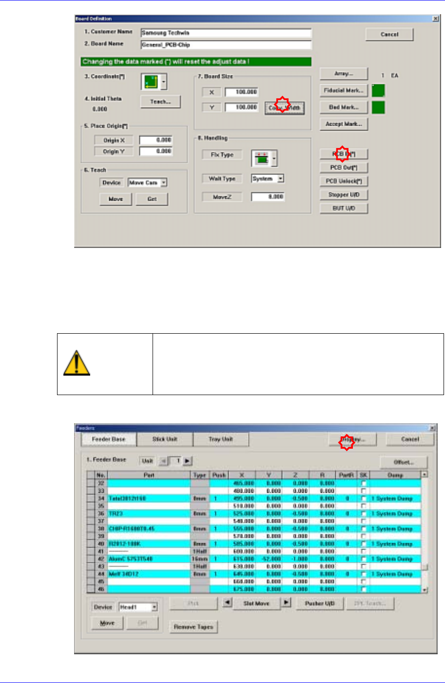
4. Adjust the conveyor width to suit the width of the board to be tested for placement.
14-2
Placement Test
14-3
5. Check if the definitions concerning other boards and related setup are correct.
(Fiducial Mark, Fix Type, MoveZ, Array, etc.)
6. Place the PCB on the conveyor so that the detection sensor located at the conveyor
inlet can recognize it and click the <PCB In> button to fix the test PCB on the
working area of the conveyor. At this time, double-sided adhesive tape may be used
on the placement surface of the PCB.
Warning
Inserting a part of body while the machine is in operation or
in temporary stop could result in severe injury.
Do not insert a part of body while the machine is in
operation or in temporary stop.
7. Install the feeder in the actual machine in the same manner referring to the setup in
the “Feeder” dialog box.