Administrator’s Guide(CP45FV) Eng.pdf - 第92页
Samsung Component Placer CP45FV Series Administrator ’ s Guide Displays the component data list of th e data selected in <Align Type> and <Part Group>. <Update Part> button After adding a New Pa…

Part Registration
7-7
<Z Pick Down> combo box: Select the speed for Z axis when the head is
lowered for component pickups.
<Z Pick Up> combo box: Select the speed for Z axis when the head is
ascending after component pickups.
<Z Place Down> combo box: Select the speed for Z axis, when the head is
lowered for placement.
<Z Place Up> combo box: Select the speed for Z axis, when the head is
ascending after placement.
Caution
In case of shock sensitive components like CSP or μBGA,
the z-axis related speed parameters must be set according
to the component manufacturer’s specification or
standards. And use the nozzle suitable to component
manufacturer’s specification or standards.
If necessary, please contact our Business Department or
the local agent for the nozzle suitable to component
manufacturer’s specification or standards.
<Register> button
Adds the set component data to the PCB part list.
<Close> button
Closes the dialog box.
<Edit…> button
Edits the selected component data.
<Duplicate…> button
Copies the selected component data. At this time, new component name must be
set.
<Copy> button
Copies the part data selected from the Part list box.
<Paste> button
Pastes the copied part data to the Part list box.
<Delete> button
Deletes the part selected in the Part list box.
<2. Library> group
Display the component list of the Local Part DB managed by the machine.
<Align Type> combo box
Select the align type of the component to be displayed. The Vision Align is used
as default.
Vision: Alignment by the Vision Camera.
<Part Group> combo box
Select the group of component to be displayed. Available component groups are
as follows.
(CHIP-Circle:, CHIP-Rect:, Melf:, TR:, Trimmer:, Hemt:, SOP:, SOJ:, SOP2:,
SOJ2:, QFP:, PLCC:, Connector-1:, Connector-2:, User IC:, BGA: )
<Part List> list box
Samsung Component Placer CP45FV Series Administrator’s Guide
Displays the component data list of the data selected in <Align Type> and
<Part Group>.
<Update Part> button
After adding a New Part, use it to add the New part to the Local DB.
<Change Group> button
Changes the group of the selected part from current part group to another group.
<Library Delete> button
Deletes the component data selected in <Part List> from the Local Part DB.
<Copy to PCB Part>
button
Copies the component data selected in <Part List> of <2. Library> group to <1. PCB
Part List> group.
<Copy to Local Part DB>
button
Copies the component data selected in the <1. PCB Part List> group to the Local Part
DB.
<Copy All to Local Part DB>
button
Copies all component data in the <PCB Part List> group to the Local Part DB.
<Cancel> button
Cancels all edited data.
Caution
If you move to another screen while editing the “Part”
dialog box, the edited data is saved automatically.
7-8
Part Registration
7-9
7.2. CHIP component data setting
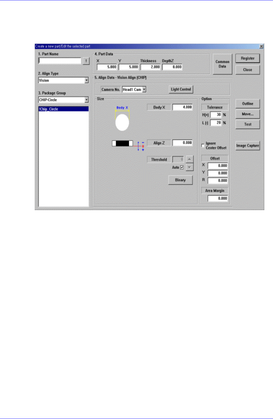
7.2.1. CHIP-Circle component data setting
Set the align data for circular CHIP components.
Figure 7-7. “Align Type = Vision,, Package Group = CHIP-Circle” dialog box
<Size> group
Set the align size.
<Body X> edit box
Set the diameter of component.
<Outline> button
Displays the outline of the component on the vision monitor by using the set align
data.
<Repeat…> button
Performs the component recognition test repeatedly. It is not explained here since it is
for debugging.
<Close> button
Ignores the set data and closes the dialog box.
7.2.1.1. Common Align Data
The following items are common to CHIP component.
<Camera No.> combo box
Select the camera to recognize the component. Available cameras are as follows.
Fix1 Cam: Fix Camera1. (If Fix Camera1 is installed)
Fix2 Cam: Fix Camera2. (If Fix Camera2 is installed)