Administrator’s Guide(CP45FV) Eng.pdf - 第171页
Optimization 10-5 <Nozzle #1 #2> list box All the nozzles used for the PCB being edite d are displayed in this list box and the status of each nozzle being the first operation nozzle or the second operation noz…
Samsung Component Placer CP45FV Series Administrator’s Guide
10.3. Setup Menu/Nozzle
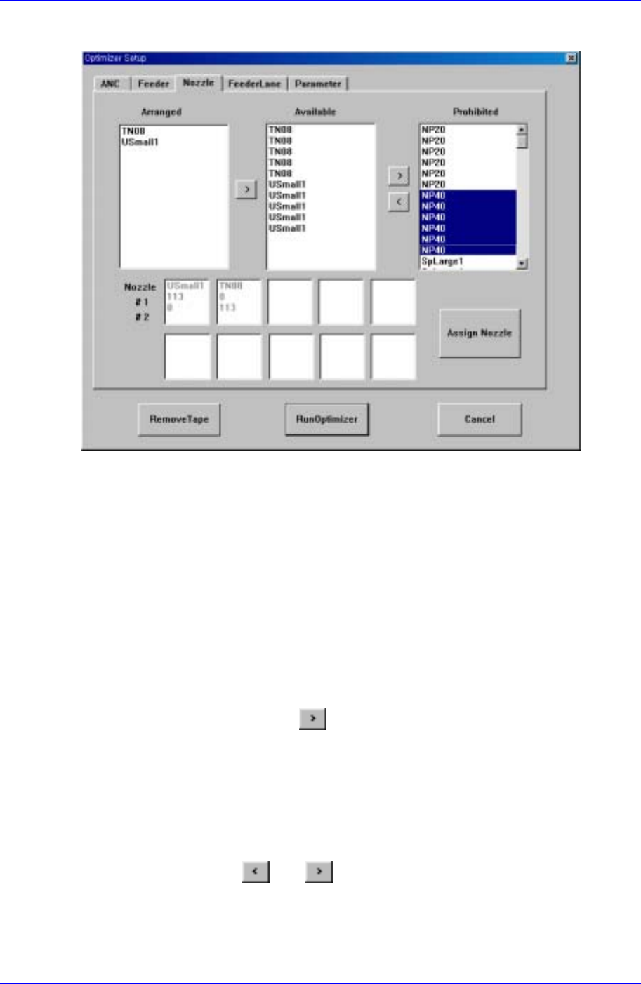
Figure 10-3. "Optimizer Setup: Nozzle" dialog box
The screen to set the optimum arrangement of nozzles.
All the nozzles registered in the equipment are displayed in the <Arranged>, <Available>,
or <Prohibited> list box. The sum of nozzles in each list box is the same with the sum of
the heads (in the case of CP45F/V, it is 6). The user can set a desired number of nozzles to
be arranged by the Optimizer by adjusting the number of nozzles in the <Available> list
box.
<Arranged> list box
The user can arrange nozzles in the ANC pocket directly in the ANC Setup Dialog
Box. The nozzles arranged in advance are displayed in the <Arranged> list box. The
nozzles listed here are used for operation but the Optimizer does not arrange them in
the pocket arbitrarily. To rearrange the nozzles already arranged by using the
Optimizer, select the desired nozzle and move it to the <Available> list box by
clicking on the arrow button (
). If the user wants to arrange the nozzle directly
again, the user needs to display the ANC Setup Dialog box and specify the pocket.
<Available> list box
The list box to specify the nozzles to be arranged in the pocket by the Optimizer.
When the Optimizer is executed, NP20 nozzle arranges in the empty nozzle pockets.
The number of nozzles to be arranged by the Optimizer can be increased and
decreased between the <Available> list box and the <Prohibited> list box by clicking
on the arrow buttons
and ..
<Prohibited> list box
This list box works like a buffer for unnecessary nozzles. The nozzles that do not
need to be rearranged can be placed in the <Prohibited> list box.
10-4
Optimization
10-5
<Nozzle #1 #2> list box
All the nozzles used for the PCB being edited are displayed in this list box and the
status of each nozzle being the first operation nozzle or the second operation nozzle
for the component is displayed at the same time. #1 indicates the sum of placement
points of the component assigned to the first operation nozzle and #2 the sum of
placement points of the component assigned to the second nozzle.
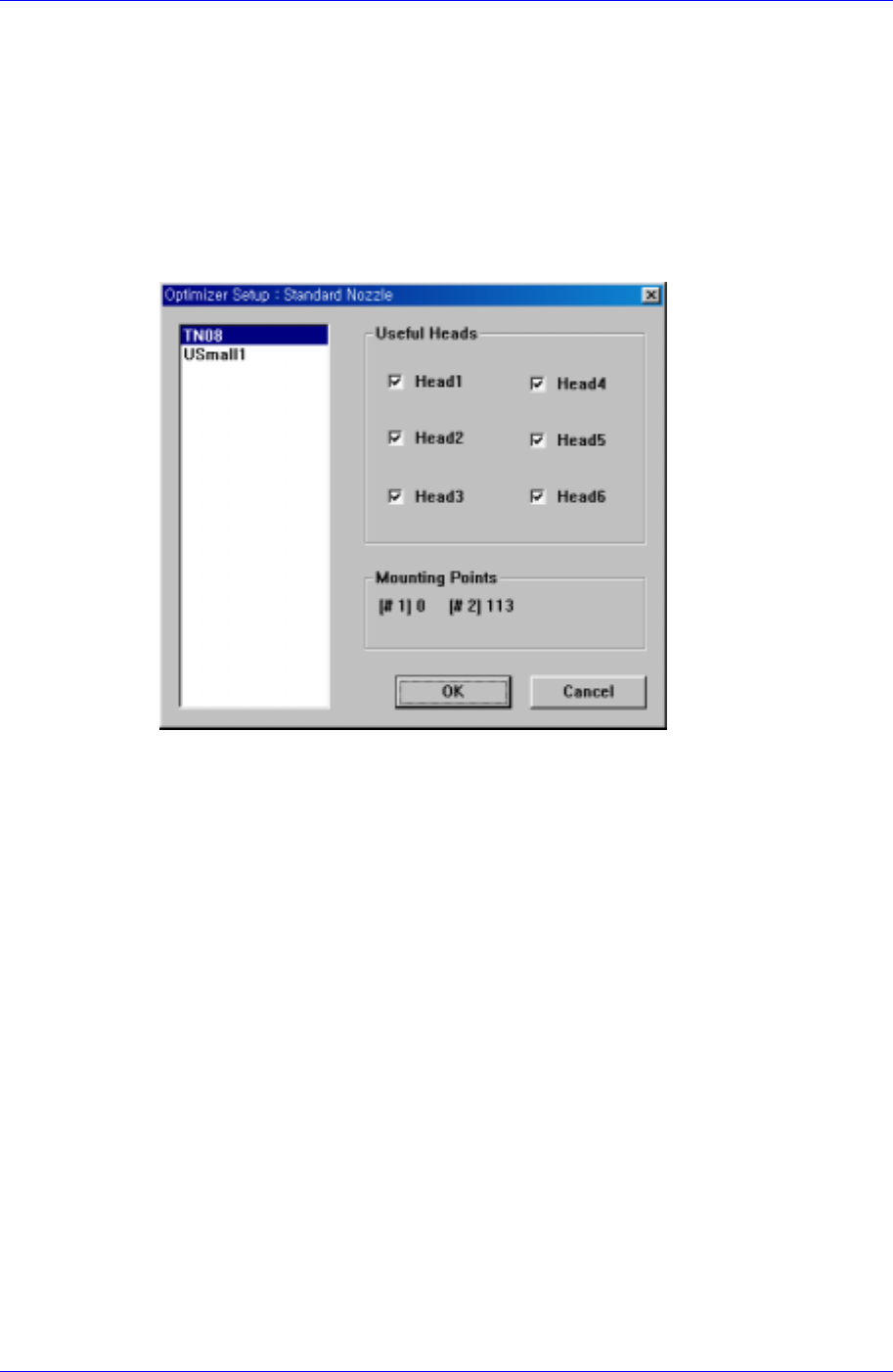
<Assign Nozzle> button
Used to assign applicable heads for each nozzle separately. When this button is
clicked on, the following dialog box is displayed.
Figure 10-4. "Optimizer Setup: Standard Nozzle" dialog box
Basically all nozzle types can be applied to any head, therefore all heads are checked.
But there are occasions when a certain nozzle has to be operated in a certain head.
Also, this can be used when the user wants to assign a certain head to a certain nozzle.
The above figure shows the nozzle TN14 can operate on any head between Head1
and Head6.
<Useful Heads> check box group
The heads that can be used by the selected nozzle type. As a standard, check so that
Head1, Head2, Head3, Head4, Head5, and Head6 can be used.
<Mounting Points> group
This group shows the number of components used by the nozzle selected for the
current PCB. This can be used as a reference data when the user assigns the
applicable heads to each nozzle. #1 shows the total number of placement points of the
component for which #1 nozzle is selected and #2 shows the total number of
placement points of the component for which #2 nozzle is selected.
Figure 10-4 shows that TN04 is selected for 1# nozzle of four components and for 2#
nozzle of two components.
<OK> button
Saves the selected options and closes the dialog box.
<Cancel> button
Cancels the selected options and closes the dialog box.
Samsung Component Placer CP45FV Series Administrator’s Guide
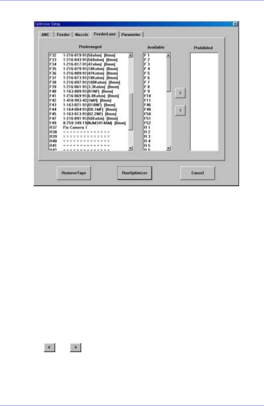
10.4. Setup Menu/Feeder Lane
Figure 10-5. "Optimizer Setup: Feeder Lane" dialog box
The screen to set the feeder lane to be used for feeder arrangement by the Optimizer. The
devices that can be arranged on the feeder lane are tape feeders, stick feeder units,
movable ANCs, camera units fixed on the feeder lane. This screen shows the current
arrangement status on each feeder lane. The feeder lanes on which devices shouldn't be
arranged in the Optimizer can be specified.
<PreArranged> list box
Displays the status of already installed feeder lanes, installed tape feeders, movable
ANCs, and cameras. The F in the feeder lane number indicates the front feeder base,
R indicates the rear feeder base.
<Available> list box
Displays the feeder lanes on which the Optimizer can arrange tape feeders.
<Prohibited> list box
Specify the feeder lanes on which you don't want to arrange any feeder unit, ANC, or
camera, so that they are displayed in this group. No device is arranged by the
Optimizer on the feeder lanes listed here. But you don't need to specify each lane in
the <Prohibited> list box while considering the width of the feeder unit, ANC, and
camera unit. The Optimizer is set to consider the width of the device to be arranged
on the feeder lane so that there is no mechanical interference. Use the arrow buttons,
and to move between the <Available> list box and the <Prohibited> list
box.
10-6