Administrator’s Guide(CP45FV) Eng.pdf - 第97页
Part Registration 7-13 <Device> combo box Selects the corresponding device to move the head assembly by rotating the driving shafts of the X and Y motors or obtains the current coordinate of the device to…
Samsung Component Placer CP45FV Series Administrator’s Guide
<Tolerance H> edit box
Set the highest tolerance with a percentage for component recognition.
<Tolerance L> edit box
Set the lowest tolerance with a percentage for component recognition.
<Ignore Center Offset> check box
In the case of Chip components, Center Offset is not checked during vision check.
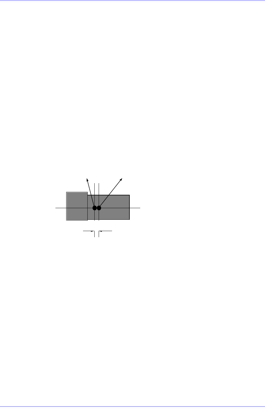
<Offset X> edit box
Set the X offset value to be added when the component is placed (After
component recognition, it is the value added after placement point adjustment). If
a component is not top/down or right/left symmetry and when the component
center(centroid) is calculated after component recognition, it does not coincide
with the actual component center. The purpose of this value is to do regular
adjustment by setting the offset value between the obtained component
center(centroid) and the actual component center.
Offset X
Component center(centroid)
after component recognition
Actual component center
<Offset Y> edit box
Set the Y offset value to be added when the component is placed. (After
component recognition, the value added after component placement point
adjustment)
<Offset R> edit box
Set the R offset value to be added when the component is placed.(After
component recognition, it is the value added after component placement point
adjustment)
<Area Margin> edit box
Sets the range for the image to be off the center of the screen when recognizing a
component. For example, if this value is set to 5mm, it means that the image
should be within 5mm of the center.
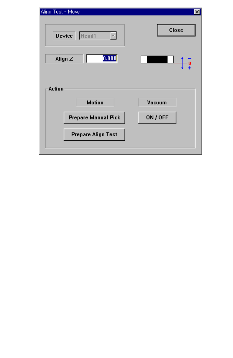
<Move…> button
Performs component pickups or moves to the fix camera. When this button is clicked
on, the following dialog box is displayed.
7-12
Part Registration
7-13
<Device> combo box
Selects the corresponding device to move the head assembly by rotating the
driving shafts of the X and Y motors or obtains the current coordinate of the
device to be selected. Applicable devices are as follows;
Move Cam: Selects the Teaching Camera.
Head1: Selects Head1.
Head2: Selects Head2.
Head3: Selects Head3.
Head4: Selects Head4.
Head5: Selects Head5.
Head6: Selects Head6.
Beam: Selects Beam.
When the <Camera No> has been set to the head camera in component align data,
the <Device> combo box is inactivated.
<Align Z> edit box
Set the height for recognition. Based on the component surface, if the top is to be
recognized, set - value, and if the bottom is to be recognized, set + value.
<Action> group
<Prepare Manual Pick> button
Moves the head block to the pickups point when the component is to be
adsorbed to the head manually. Moves to the Home position of the machine.
<Prepare Align Test> button
Prepares for the component align test. If the <Camera No.> to be aligned is
the fly camera, moves the Z axis of the head to the align height, closes the
Samsung Component Placer CP45FV Series Administrator’s Guide
mirror and sets the light. If the <Camera No.> to be aligned is the fix camera,
moves the Z axis of the head to a safe height, moves the head block to the fix
camera position, and then moves the Z axis of the head to the align height.
<Vacuum ON/OFF> button
Turns on/off the vacuum generator of the head for component pickups or
release.
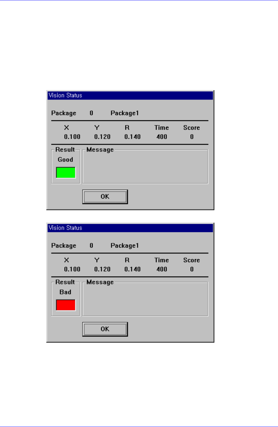
<Test> button
Tests component recognition by using the set align data. When the test is successful,
the following message box is displayed.
When the test is not successful, the following message box is displayed.
<Image Capture> button
Helps to specify the optimum lighting value. The lighting is gradually changed
automatically and the images are saved. The user can check the best image and
identify the optimum lighting value.
7-14