Administrator’s Guide(CP45FV) Eng.pdf - 第84页
在线预览 Administrator’s Guide(CP45FV) Eng.pdf PDF 文档。
Board Definition
6-23
<8. Parameter> group
<Threshold> edit box
Set the threshold value of <Bad Mark Logic> when testing the Accept Mark.
For example, if <Accept Mark Logic> is “Black” and the <Threshold> value
is 100, all values under 100 in the vision image are recognized as black. And
if <Accept mark Logic> is “White” and the <Threshold> value is 100, all
values over 100 in the vision image are recognized as white. On the vision
display, the image for which the threshold value is applied is in the binary
mode and the image for which the threshold value is not applied is the real
display.
<Light> group
Set the lighting value when testing the Accept Mark. In general, set to 7.
However, adjust it properly according to the condition of the PCB and accept
mark.
<Test> button
Tests the mark by using the set mark data. The user can check whether the set
mark data is correct.
<PCB In> button
Loads the PCB in the operation area.. Before executing this function, the PCB
arrangement method must be set in “Fix Type” of <7. Handling>.
<PCB Out> button
Releases the PCB fixed in the operation area.
<Stopper U/D> button
Moves up or down the work stopper, the stopper of PCB in the operation area.
<BUT U/D> button
Moves up or down the BUT(Back Up Table) that locks up the PCB in the operation
area.
<Cancel> button
Cancels the edited data.
Caution
If you move to another screen while editing the “Board”
dialog box, the edited data is saved automatically.
Part Registration
Chapter 7. Part Registration
7-1
7.1. Part [F3]
The <Part> command is used to register components necessary for PCB operation and
edit data.
The component data managed by this machine include PCB Part, Local Part Library, and
Standard Part DB. The following is the structure of each data and the relationship
between these data.
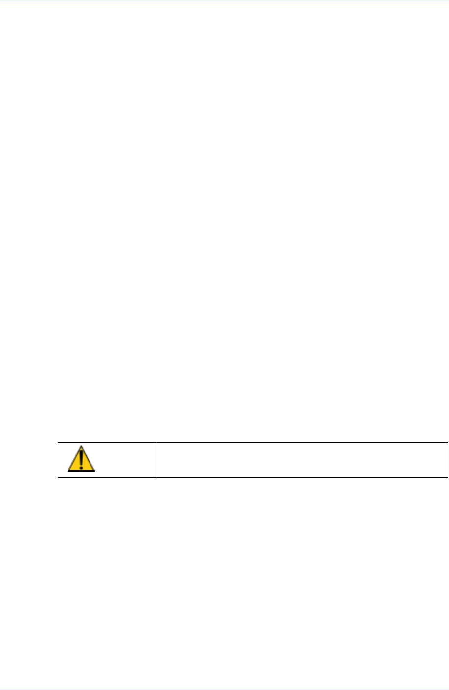
Figure 7-1. Component Data Structure
The component data in the Figure 7-1 is composed of “Part” that controls component
names and component sizes and “Common Package” that has the data related to the
machine.
The align type is setup according to the way a component shape is recognized. However,
the “Vision Align” recognizes component shape through a vision camera. The controlled
data are different depending on each align type. The vision align type is classified as
“Vision Align Package”. Set the align data to be applied now in the Align Type of “Part”.
In the Figure. 7-1, “Vision Align Package” is being set with the current align data.
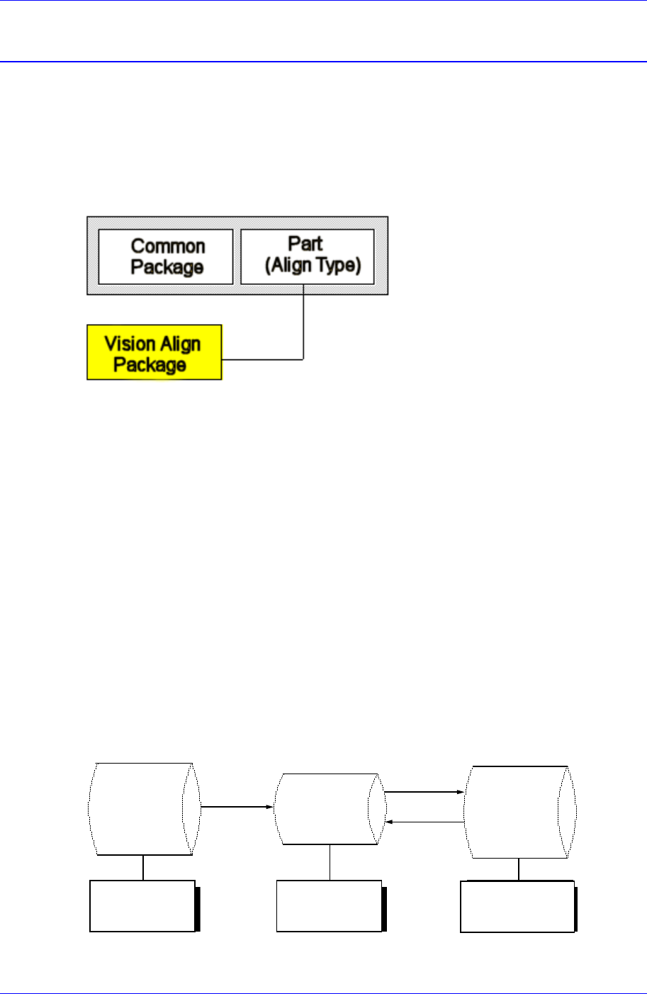
Each PCB controls component data on all components operated on the corresponding
PCB and saves the component data in the Local Part DB of the machine. To create
component data for a new PCB, component data stored in the Local Part DB can be
copied. To create component data for a new component whose data is not stored in the
Local Part DB, data for a similar component stored in the Local Part DB can be copied
and edited or standard component data can be copied from the Standard Part DB and
edited. The Standard Part DB is a DB of generally used components developed and
supplied by this machine manufacturer. The relationship between component data is
shown in the following.
Standard
Part DB
PCB Part
Local
Part DB
Create
New
p
ar
t
Save
Copy
Applied to
all PCBs
Controlled by
each PCB
Controlled by
each machine
Figure 7-2. . Relationship between component DBs