Administrator’s Guide(CP45FV) Eng.pdf - 第190页
Samsung Component Placer CP45FV Series Administrator ’ s Guide Head5: Selects Head5. Head6: Selects Head6. <Move> button Moves the XY axis to the device sel ected in the <Device>. Th…
ANC Menu
Chapter 12. ANC Menu
12-1
The ANC menu performs functions related to ANC setting including the arrangement of
nozzles on the ANC(Auto Nozzle Changer), nozzle pickups, and attachment. When this
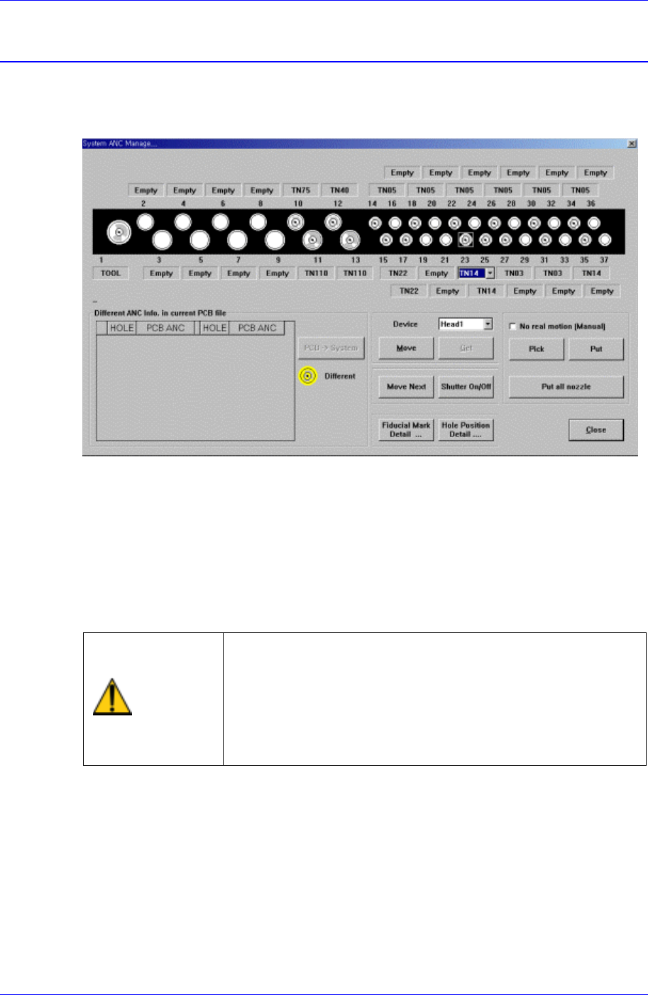
button is clicked on, the following dialog box is displayed.
Figure 12-1. “ANC Setting…” dialog box
<Select> option button
Select the ANC number to set.
<Different ANC Info.In Current PCB file> list box
Shows the difference between the ANC setting of the currently loaded PCB file and
the ANC setting of the currently working machine system. To change the system
setting to the PCB file setting, click on the <PCB->System> button on the right and
change the nozzles in other holes with different settings to fit the setting.
Warning
When the nozzle is needed to arrange manually, Open the
ANC shutter using <Shutter On/Off> button and after
pushing the <EMG> switch in the front operation panel or
in the rear operation panel, arrange the nozzle manually.
And release the <EMG> switch and push the <Reset>
switch. If this procedure is not followed, personal injury
could occur. Be sure to follow this procedure.
<Device> combo box
To move or to read in the position of the XY axis, select the corresponding device.
Available devices are as follows.
Move Cam: Selects Teaching Camera.
Head1: Selects Head1.
Head2: Selects Head2.
Head3: Selects Head3.
Head4: Selects Head4.

Samsung Component Placer CP45FV Series Administrator’s Guide
Head5: Selects Head5.
Head6: Selects Head6.
<Move> button
Moves the XY axis to the device selected in the <Device>. The positions to move to
are the positions of fiducial mark and each nozzle hole.
<Get> button
Reads in the current position of the XY axis of the device selected in the <Device>.
At this time, the position to be read is the position of the fiducial mark. The position
of each nozzle hole can be read with the “Get” button.
<Move Next> button
When this button is clicked on, moves the device selected in the “Device” to the next
hole of the currently selected hole of the ANC.
<Shutter On/Off> button
When this button is clicked on, the ANC shutter is turned on or off.
<No real motion> check box
When this button is checked, manipulates the data for pick and put functions without
actual operation.
<Pick> button
When this button is clicked on, picks up the nozzle in the currently selected hole of
the ANC. Select the head to pick in the “Device”.
<Put> button
When this button is clicked on, puts the nozzle in the head selected in the “Device” to
ANC.
<Put all nozzle> button
When this button is clicked on, puts the nozzles in all the heads to the ANC.
<Name> edit box
Set the name of ANC.
<Installed> group
In the case of installing the ANC on the feeder base, set the feeder base and lane to
install. The group is activated only for the gripper ANCs.
<Feeder Base> combo box
Select the feeder base to install the ANC.
<Lane No.> edit box
Set the lane number of the feeder base to install the ANC.
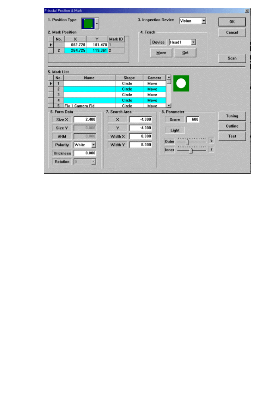
<Fiducial Mark Detail …> button
Set the fiducial mark data. When this button is clicked on, the following dialog box is
displayed.
12-2
ANC Menu
12-3
For the explanation of this dialog box, please refer to [PCB Edit].
<Hole Position Detail …> button
Set the position of each hole of the ANC. When this button is clicked on, the
following dialog box is displayed.