Administrator’s Guide(CP45FV) Eng.pdf - 第228页
Samsung Component Placer CP45FV Administrator ’ s Guide If the component recognition is failed, click the <Edit Part Info> button to change the Align Data for the corresponding component. At this time, if the c…
Placement Test
14-13
14.3.4. Component Recognition Error
Occurs when the component is not recognized through the vision system. Generally, it
occurs when the registered component data or the lighting for component recognition is
inappropriate.
When the component recognition error occurs, stop the work and perform test pickup
for the component to which the error occurred and check the align data.
The following example assumes that an error occurred when the Head 1 picked up the
‘Tantal3012t160’ component fed to the 8mm Tape Feeder mounted on the No. 34 slot.
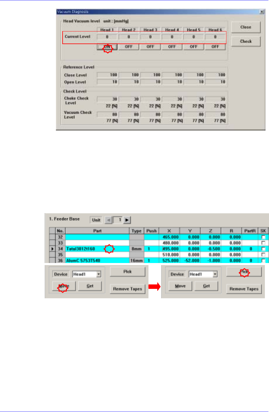
Select the feeder mounted on the No. 34 slot in the “Feeder” dialog box with the
component mounted on the Head 1.
If the <Move> button is clicked after selecting the Head 1 in the <Device> combo
box, the Head 1 moves to the placement point of the corresponding feeder.
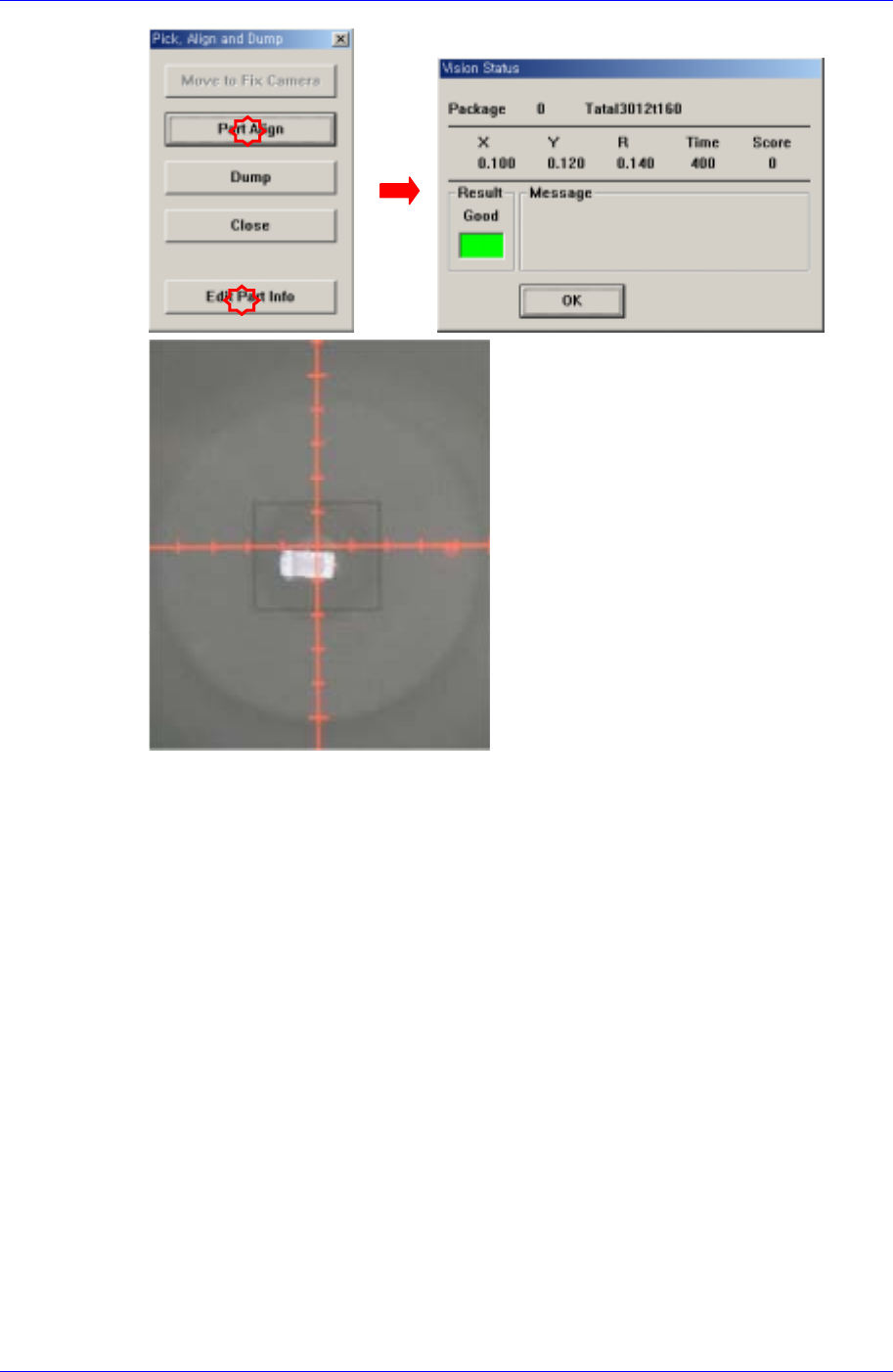
If the <Pick> button is clicked, the following dialog box is displayed. When the <Part
Align> is clicked in the dialog box, the machine will perform component recognition.
If the component is recognized successfully, the following “Vision Status” window is
displayed.
Samsung Component Placer CP45FV Administrator’s Guide
If the component recognition is failed, click the <Edit Part Info> button to change the
Align Data for the corresponding component.
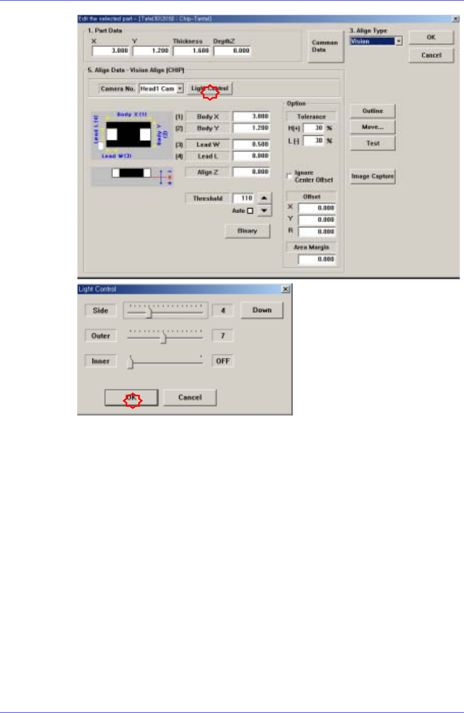
At this time, if the component is not clearly seen on the vision monitor as in the
above figure, click the <Light Control> button in the following dialog box to adjust
the lighting by controlling the slide bar so that the component shape can be seen
clearly.
14-14
Placement Test
14-15
Click the <OK> button to apply the changed lighting value to the corresponding
component profile, and click the <Part Align> button to perform component
recognition again.
If the component is still not recognized, click the <Edit Part Info> button again to
change the Align Data for the corresponding component.
For more details concerning the component profile change, refer to the “7.1 Part
[F3](page 7-1)”.
Once the component profile is changed, click the <OK> button in the “Edit the
selected part” dialog box to apply the change, and click the <Part Align> button to
perform component recognition again.
14.3.5. Component Placement Error
Occurs in the following cases; the nozzle has a defect; the component placement height
setup is incorrect; the air blow or vacuum function is not working properly; and the
placement related parameter setup is inappropriate.
When the nozzle has defect
Error occurs if a standard genuine nozzle is not used or the nozzle is clogged with
foreign matter or the nozzle suitable to the component is not used.