Administrator’s Guide(CP45FV) Eng.pdf - 第225页
Placement T est 14-1 1 vacuum for component pickup is differe nt from the actual component pickup height. Reference Surface Z = 0 Paper Ta p e Embossed Ta p e The Z value of the pickup point is applie d in various ways a…
Samsung Component Placer CP45FV Administrator’s Guide
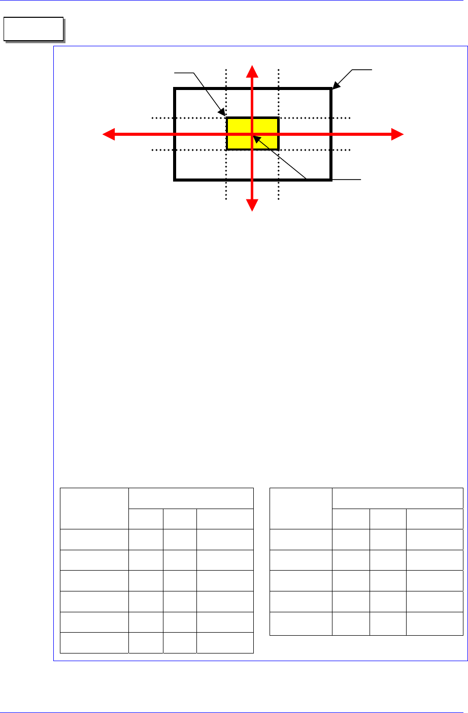
1. On 1/3 area of component pocket
First, check if the feeder is normally installed on the feeder base. If a feeder is installed
while a chip is stuck on the feeder base, the pickups position will be deviated to that
extent.
It is all right to use the feeder position (or pickups position) without changing it if the
crossing point of the red arrows on the vision monitor is within 1/3 area of component
pocket. When the feeder is installed normally, but the pickups position and the crossing
point of the red arrows are on the outside of 1/3 area of component pocket, the feeder is
considered to be abnormally installed. In this case, change the feeder, teach again, and
install it.
2. Component pickups point
Do not change the component pickups position if possible. Use the original coordinate
and it is recommended to use a value between 0.00 and 0.50 for Z axis coordinate.
3. Data value for normal chip components (1005 ~ 3216)
The machine speed and time delay when registering regular chip components are
as follows. The data differs according to the chip size. As chip components 0603
and 1005 are tiny, it is best to place them under a condition different from the one
for other chip components. However, they are not absolute. Rather, it is best to use a
value in these ranges to avoid putting strain on the machine.
Component pocket
area
Memo
1/3
2/3
1/3
2/3
1/3 area of component
pocket
Crossing point of the red
arrows on the vision
monitor
Speed
Item
0603 1005 1608~3216
XY 1 1 1
R 1 1 1
Z Pick down 1 3 1
Z Pick up 3 2 1
Z Place down 1 1 1
Z Place up 1 1 1
Time Delay
Item
0603 1005 1608~3216
Pick up 0 20 30
Place 25 25 10
Vacuum off 0 0 0
Dump 100 100 100
Vacuum vac.
off
0 0 0
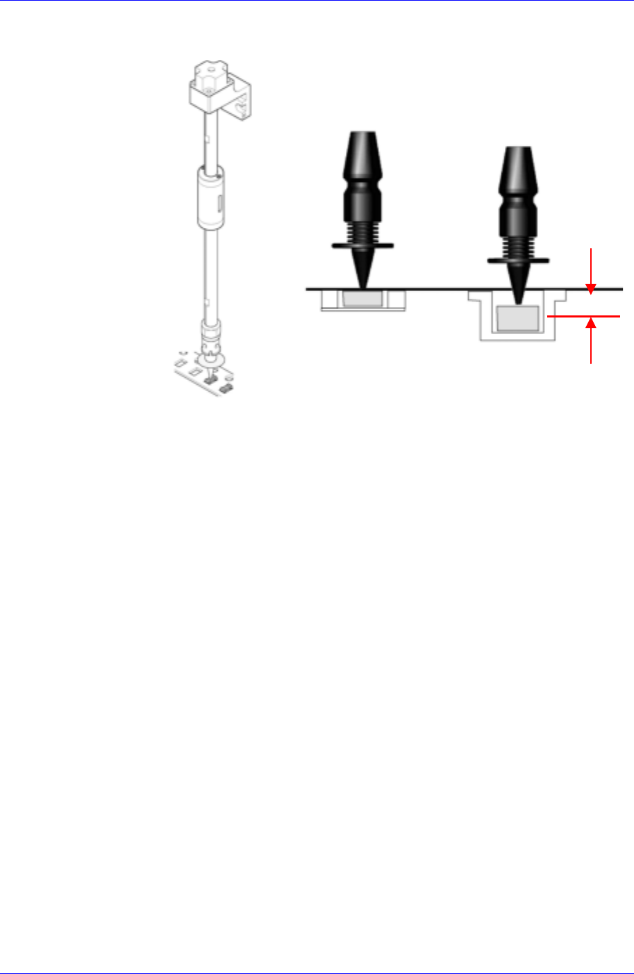
When the component pickup height is different
The error occurs when the pickup height at which the machine turns on the
14-10
Placement Test
14-11
vacuum for component pickup is different from the actual component pickup
height.
Reference
Surface
Z = 0
Paper
Tape
Embossed
Tape
The Z value of the pickup point is applied in various ways according to the types
of tape feeders. In addition, it varies depending on the types of supplied tape. In
the case of the embossed tape, the height must be set lower than that of the paper
tape.
For embossed tape, set the Z value of the pickup point properly referring to the
component tape standards.
Nozzle Defect
Occurs when a standard nozzle is not used or the nozzle is clogged with foreign
matter or a nozzle suitable to the component is not used.
If the standard genuine nozzle is not used, vacuum is not created properly
and the component may not be picked up. Therefore, a standard genuine
nozzle must be used.
When the nozzle is clogged, clean the nozzle referring to the “2.1 Nozzle” of
the Maintenance Reference.
Use only the nozzle suitable to the component referring to the following table.
Samsung Component Placer CP45FV Administrator’s Guide
Nozzle
name
Minimum
component
width
Major component types
TN-03
0.3 ~ 1.5 0603,1005 Only
TN-04
0.5 ~ 1.25 1005, 1608, 2012,3216, SOT(Molded part 0.8 X 1.6)
TN-065
0.8 ~ 2.5 1608, 2012, 3216, MELF(Molded part 1.2 X 2.0), SOT23
TN-14
2.5 ~ 4.0
Aluminum electrolytic capacitor(Small), Tantalum capacitor,
Trimmer
TN-22
4.0 ~ 7.0
Aluminum electrolytic capacitor(Medium), SOP(Narrow), SOJ,
Connector
TN-40
7.0 ~ 10.0
Aluminum electrolytic capacitor(Large), SOP(Wide), TSOP,
QFP, PLCC, SOJ, Connector
TN-75
10.0 ~ QFP(Medium), PLCC(Medium)
TN-110
20.0 ~ QFP(Medium), PLCC(Large)
CN20 Calibration Tool(Nozzle) for Flying Vision
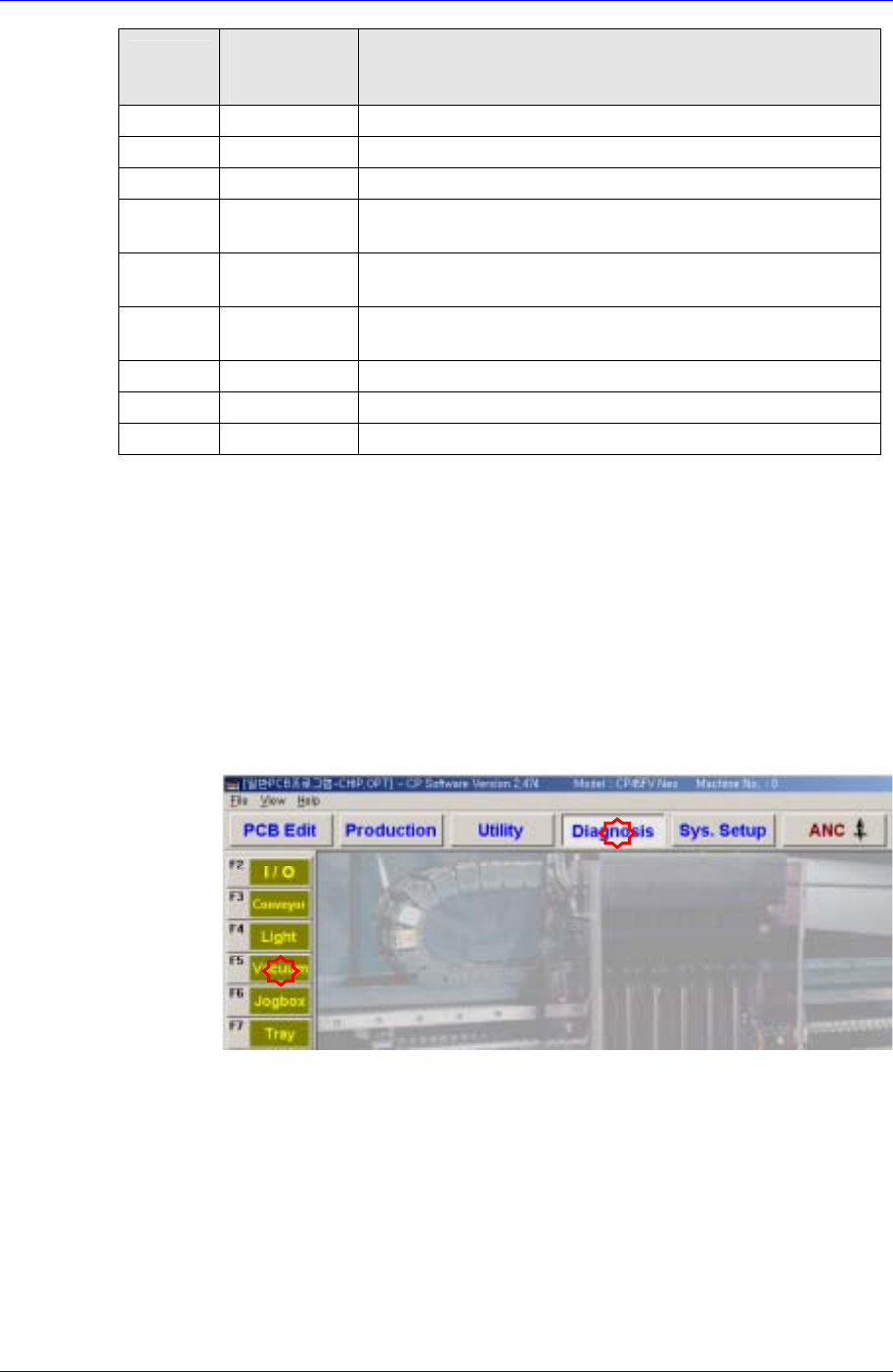
Vacuum Defect
Occurs when the vacuum of the corresponding head is not created normally.
Check if the vacuum of the corresponding head is normal.
Select the “Diagnosis” menu and then select the submenu of the “Vacuum”
menu at the left of the screen.
Check if the current vacuum level is higher than 600mmHg by turning on the
vacuum clicking the <ON> button of the corresponding head in the
<Vacuum Diagnosis> dialog box with the nozzle tip covered with a finger.
If the current vacuum level is below 600mmHg, there is a problem with the
vacuum function. Contact our designated CS company (STS) or local agent.
14-12