Administrator’s Guide(CP45FV) Eng.pdf - 第63页
Boar d Definition 6-3 This button is used to teach the initial th eta of PCB. When this button is clicked on, the following screens are displayed in succession. When teaching the initial theta of PCB, teach two points on…
Samsung Component Placer CP45FV Series Administrator’s Guide
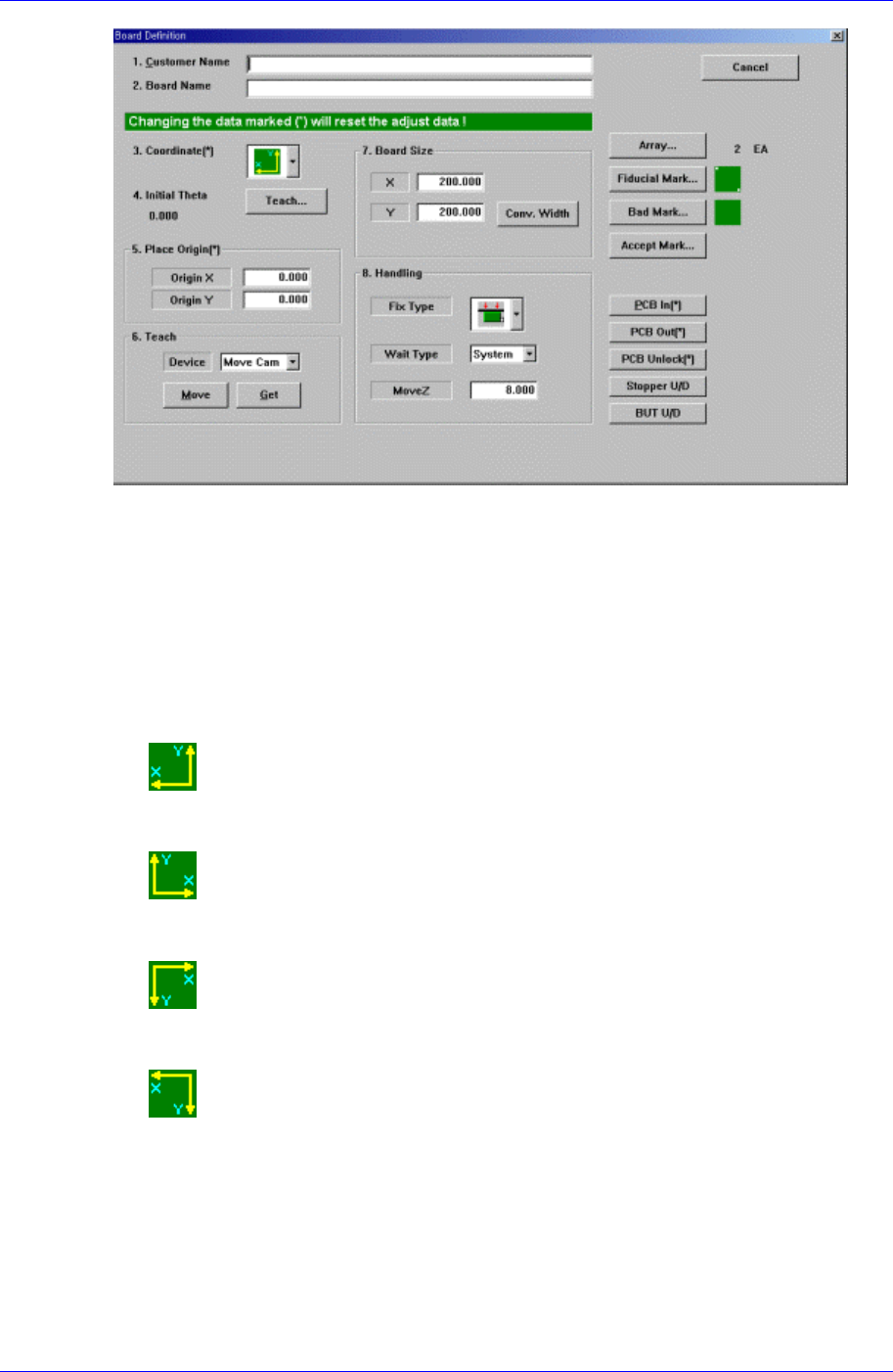
Figure 6-4. “PCB Edit : Board Definition” dialog box
<1. Customer Name> edit box
Enter the name of the customer who requested the PCB operation. Up to 64
characters can be entered.
<2. Board Name> edit box
Enter the PCB name. Up to 64 characters can be entered.
<3. Coordinate> combo box
Select the PCB coordinate system. Available coordinate systems are as follows.
Left-Up : Based on the front of machine, it is a coordinate system in which the
X axis increases to the left and the Y axis increases to the top.
Right-Up : Based on the front of machine, it is a coordinate system in which
the X axis increases to the left and the Y axis increases to the top.
Left-Down : Based on the front of machine, it is a coordinate system in which
the X axis increases to the left and the Y axis increases to the top.
Right-Down : Based on the front of machine, it is a coordinate system in which
the X axis increases to the left and the Y axis increases to the top.
<4. Initial Theta >
Set the initial theta for board data editing. At this time, the PCB should be already
loaded in the working area of the machine.
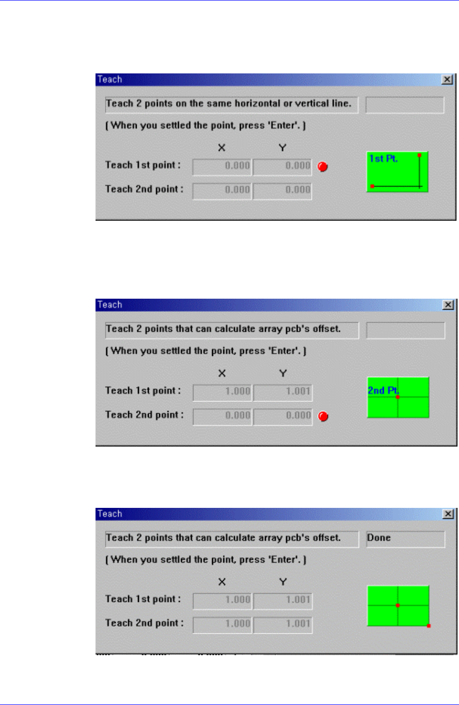
<Initial Theta - Teach> button
It is activated when there is fiducial mark data.
6-2
Board Definition
6-3
This button is used to teach the initial theta of PCB. When this button is clicked
on, the following screens are displayed in succession.
When teaching the initial theta of PCB, teach two points on the same horizontal
or vertical line, then the initial theta of the PCB is calculated automatically.
Figure 6-5. Screen showing the first point teaching
Teach the first point of the two points on the same horizontal line or vertical line
on the PCB. When the “Enter” key is pressed after teaching, the following screen
is displayed.
Figure 6-6. Screen showing the second point teaching
Teach the second point of two points on the same horizontal or vertical line on
the PCB. When the “Enter” key is pressed after teaching, the following screen is
displayed.
Figure 6-7. Screen showing completion of teaching operation
After teaching the two points, press “Enter” to complete the initial theta teaching
Samsung Component Placer CP45FV Series Administrator’s Guide
operation.
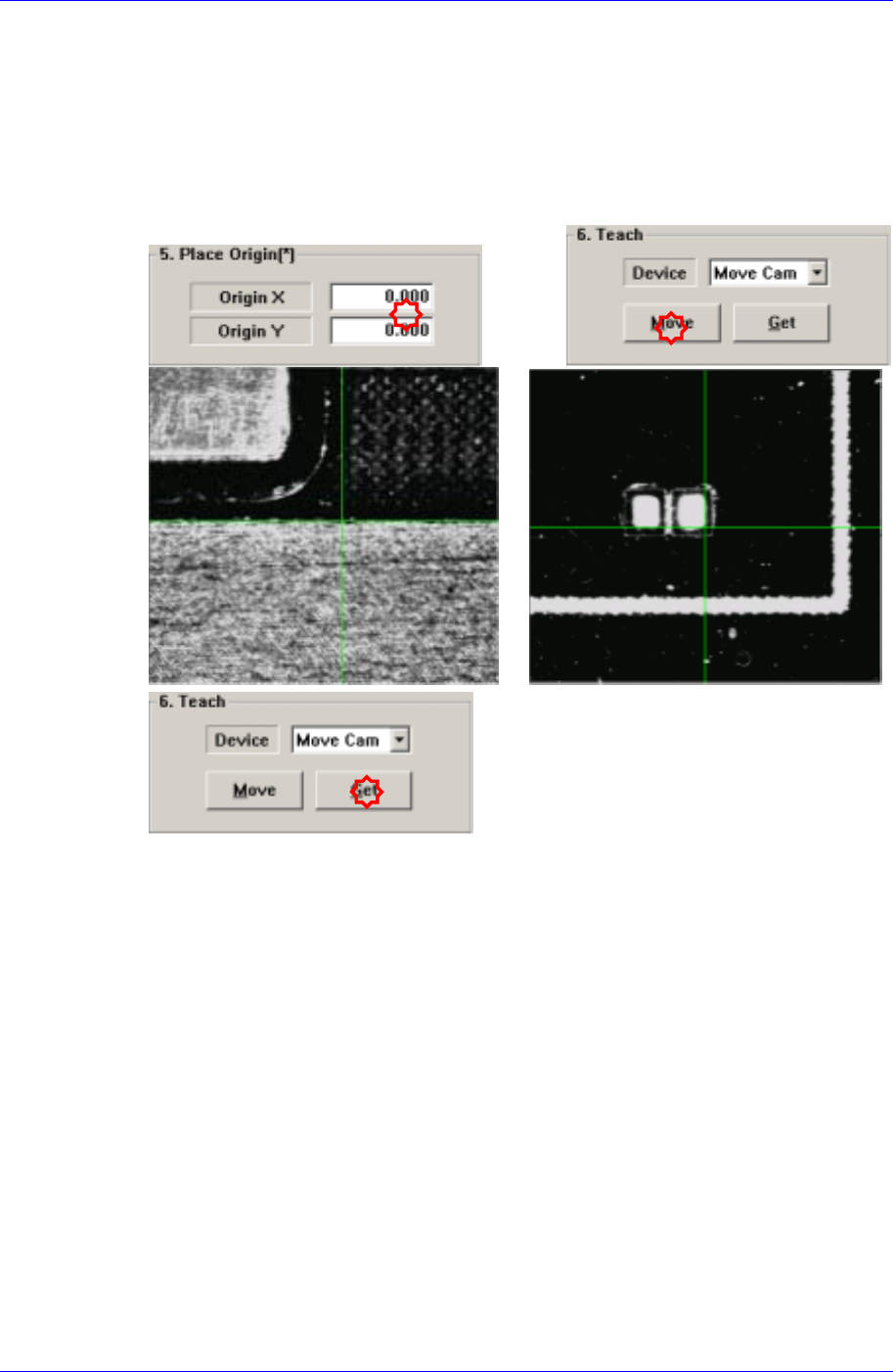
<5. Place Origin> group
Set the placement origin of PCB. This origin is defined by the offset from the PCB
origin of the system to the placement origin of PCB. This is to set the reference point
of the board to work on based on the set coordinate. Generally, the reference point is
setup by choosing the pattern near the stopper. Set the reference point at the location
in the board that can be easily confirmed.
<Origin X> edit box
Set the X value of the placement origin of PCB.
<Origin Y> edit box
Set the Y value of the placement origin of PCB. Click on <Origin X> or <Origin
Y>, then click on the “Move” or “'Get” button in the <8. Teach> group, Teaching
of the placement origin can be done using the device selected from the <Device>
combo box.
<6. Teach> group
Used to move the head assembly or spindle to the set position by rotating the shafts of
the X, Y and Z-axes driving motors or to obtain the current shaft locations of the X, Y
and Z-axes driving motors.
<Device> combo box
Used to select the corresponding device when moving the head assembly by
rotating the shafts of the X, Y and Z-axes driving motors or to obtain the current
coordinate of the device to be selected. Available devices are as follows;
Move Cam: Selects Teaching Camera..
Head1: Selects Head1.
6-4