Administrator’s Guide(CP45FV) Eng.pdf - 第280页
Samsung Component Placer CP45FV Administrator ’ Guide 5. Click the <Update> button to reflect the changed value. <Communication> group Set the data related to RS-232C communication. <Channel> combo bo…
System Setup
16-13
<Name> edit box
Set the name of the selected tray feeder unit.
<Type> combo box
Select the type of the set tray feeder unit. Available types are as follows.
Single Tray: Tray to be installed on the feeder base.
FW-20F: Tray consists of 20 step Palette, it communicates with the machine through
RS-232C.
FW-20S: Tray consists of 20 step Palette, it communicates with the machine though
RS-232C.
NONE: Means no tray is installed.
<Use Non Stop Function> check box
This will be activated if the FW-24XS Tray Feeder is selected from the <Type>
combo-box. Put a tick mark to use the ‘Non stop’ function.
<Origin> group
Set the origin of the selected tray feeder unit. This origin is the offset value from the
machine origin. It sets the left or right point as shown in the following figure.
Set the Tray Feeder Origin as follows;
1. In case the origin is not set after the Auto Tray is installed, since the tray
coordinate of the existing program changes when the tray is inserted again after
removal, its teaching must be performed again.
If the teaching of the origin is performed after the tray feeder has been installed
initially, the pickup point coordinate of the existing feeder need not be changed
individually if the coordinate of the initial teaching is reset as origin when the
tray is inserted again after removal.
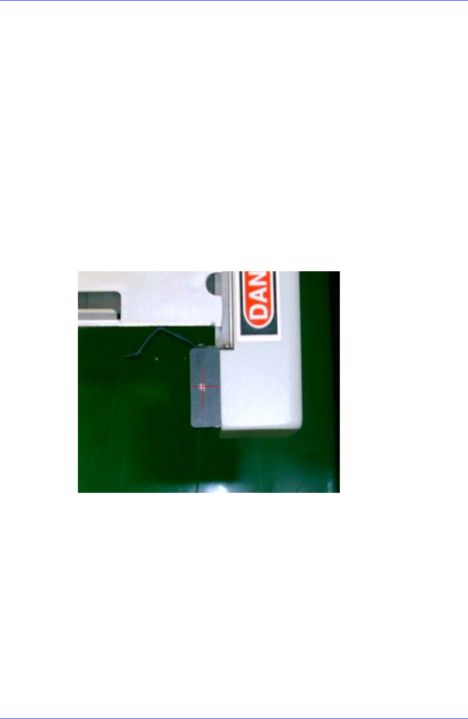
2. In order to move the Move Camera (Fiducial Camera) to the origin of the tray,
select “Move Cam” in the <Device> combo box and click the <Move> button.
3. Using the teaching box, align the set point on the tray on the cross hair center of
the Move Camera (Fiducial Camera) shown on the vision monitor accurately.
4. Select the <Origin> group using the mouse and click the <Get> button to enter
the current coordinate in the <Origin> group.
Samsung Component Placer CP45FV Administrator’ Guide
5. Click the <Update> button to reflect the changed value.
<Communication> group
Set the data related to RS-232C communication.
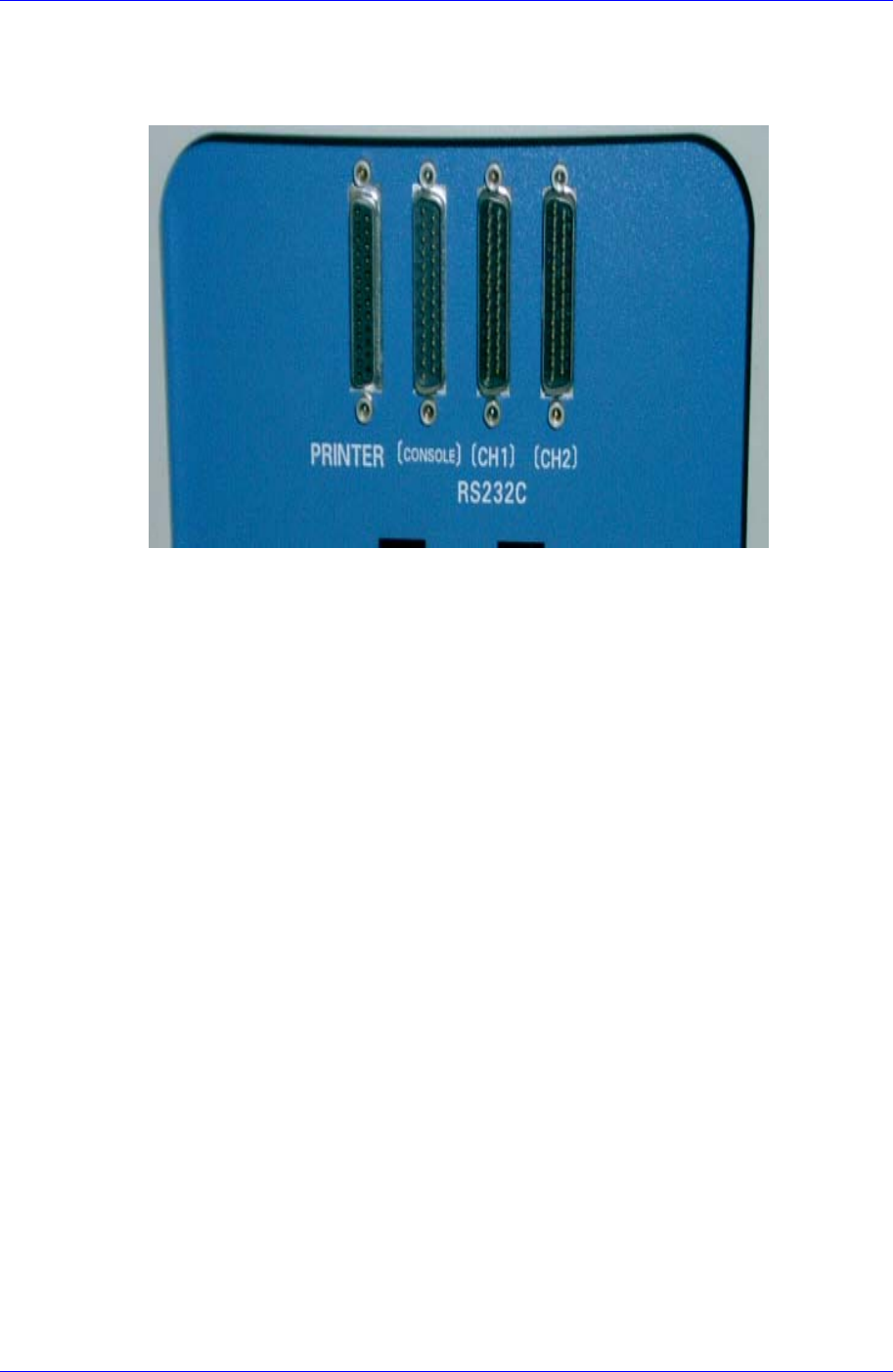
<Channel> combo box
Select the RS-232C communication channel. Two channels are available for the
machine.
<Comm. ID> combo box
Select the communication ID. Available IDs are 1 – 3. Perform the setups in
order to avoid duplication.
<Not Usable Lane> group
To use the selected tray feeder unit, set the feeder base unit and slot taken up by the
corresponding tray.
<Feeder Base> combo box
Select the feeder base. In the case of the CP45FV model, available feeder bases
are Front( front Feeder Base), and Rear( rear Feeder Base).
<Lane> edit box
Set the slot of the feeder base.
<Fiducial> button
At the moment, it does not have a function.
<Device> combo box
Selects the corresponding device to move the head assembly by rotating the driving
shafts of the X, Y and Z-axes motors, move or rotate the spindle or obtain the current
coordinate of the device to be selected. Available devices are as follows;
Move Cam: Selects Teaching Camera.
Head1: Selects Head1.
Head2: Selects Head2.
Head3: Selects Head3.
Head4: Selects Head 4.
16-14
System Setup
16-15
Head5: Selects Head5.
Head6: Selects Head6.
Beam: Selects Beam.
<Move> button
Moves the head assembly by rotating the shafts of the X, Y and Z-axes driving
motors using the device selected from the <Device> combo box. At this time, the edit
box corresponding to the position to move to must be clicked on with a mouse.
<Get> button
Reads in the XY and Z axis of the device selected in <Device>. At this time, the edit
box corresponding to the position to be read must be clicked on with a mouse.
<Update> button
Transmits the set data to the machine and closes the dialog box.
<Cancel> button
Ignores the set data and closes the dialog box.
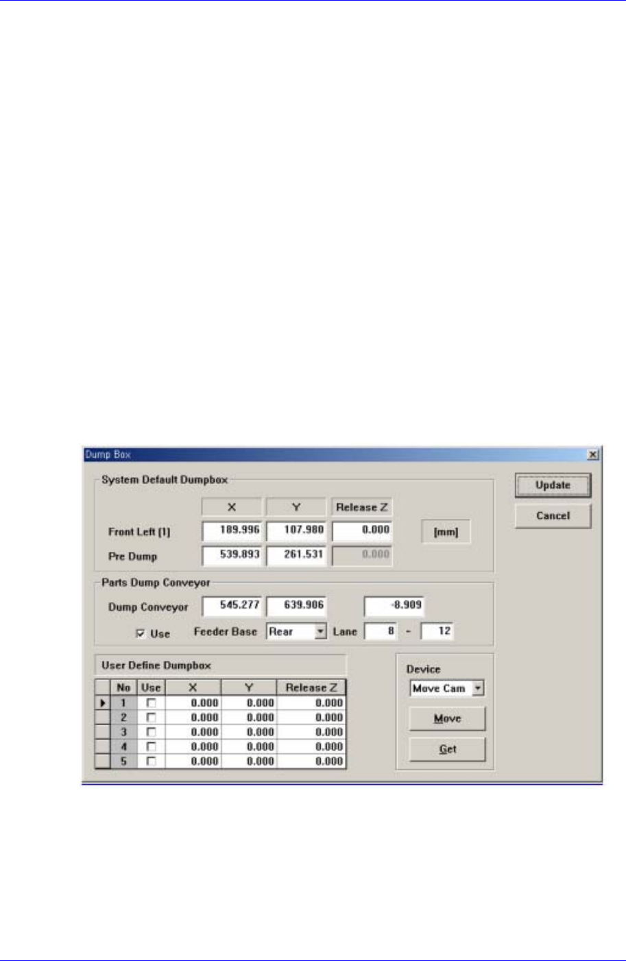
16.6. Dump [F7]
Sets the data on the dump box where the picked up components are dumped.
When this button is clicked on, the following dialog box is displayed.
Figure 16-8. “Sys. Setup : Dump Box” dialog box
<System Default Dumpbox> group
Set the data on the system dump box provided by the System as a default. 2 system
dump boxes are installed on the conveyor guide located close to the front of the
machine as a default.
<Position X, Y – Front Left(1)> edit box
Set the position of the system dump box 1(Located on the left of the conveyor