Administrator’s Guide(CP45FV) Eng.pdf - 第132页
在线预览 Administrator’s Guide(CP45FV) Eng.pdf PDF 文档。
Part Registration
7-47
Please refer to “7.2.1.1 Common Align Data (Page 7-9)” for more information.
<Test> button
Performs the component recognition test by using the set align data. Please refer to
“7.2.1.1 Common Align Data (Page 7-9)” for more information.
<Image Capture> button
Helps to specify the optimum lighting value. The lighting is gradually changed
automatically and the images are saved. The user can check the best image and
identify the optimum lighting value.
Please refer to “7.2.1.1 Common Align Data (Page 7-9)” for more information.
Feeder Setup
Chapter 8. Feeder Setup
8-1
8.1. Feeder [F4]
The <Feeder> command edits data related to tape feeder, stick feeder, and tray feeder.
The user can specify the part to be installed on each feeder, teach pickups position, and
test component pickups. When this command is selected, the initial screen is for the tape
feeder screen.
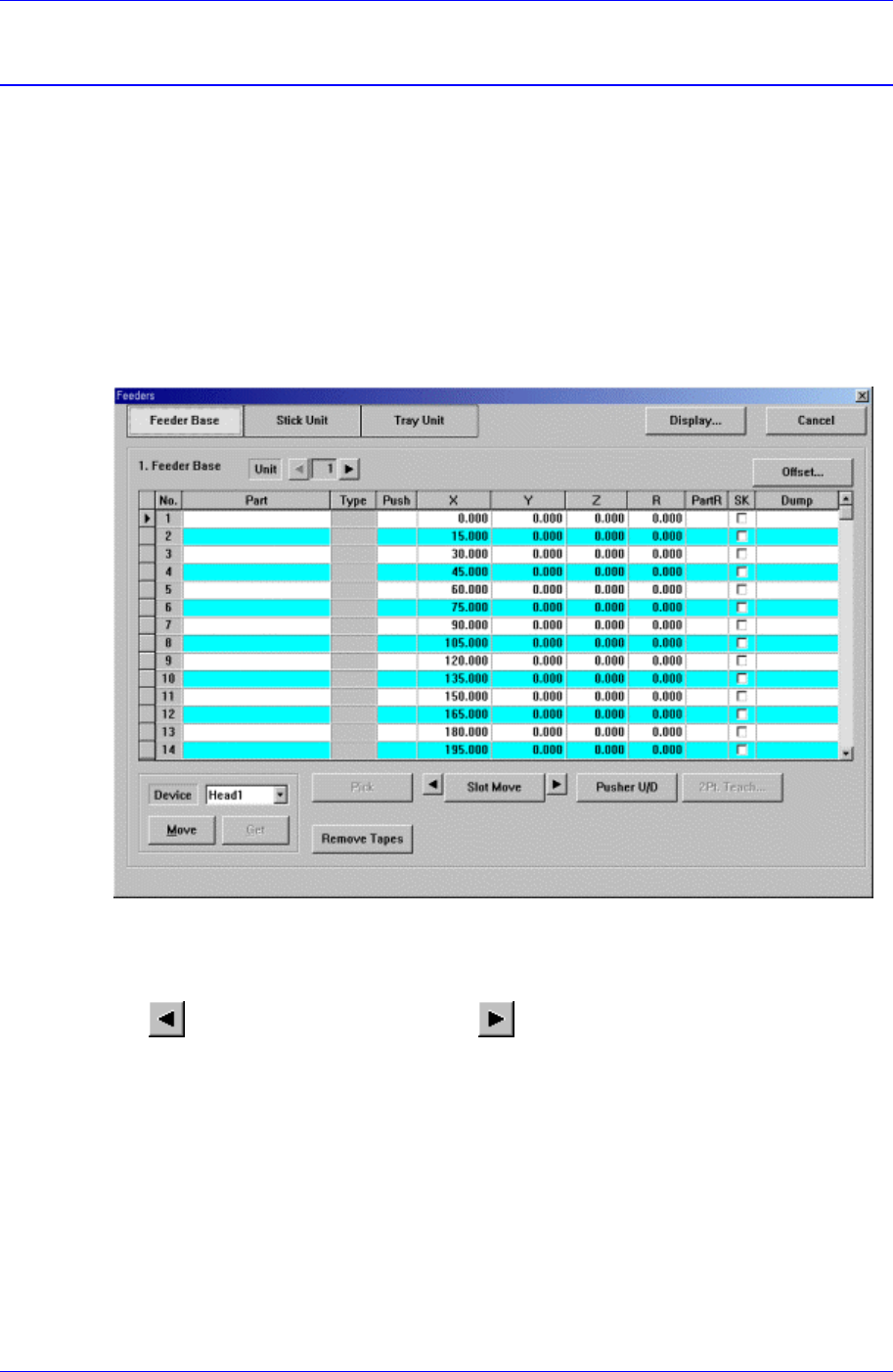
8.1.1. Feeder Base
When the feeder base is selected, the following dialog box is displayed and the data on
feeder base can be edited.
Figure 8-1.. “Feeder : Feeder Base” dialog box
<Unit> group
Select the feeder base unit to edit.
button selects the previous unit, button selects the next unit.
<1. Feeder Base> group
Display the status of various devices installed on the feeder base including the feeder
type and edit the installation position.
<No> column
A serial number of the feeder base slot. Air pressure type feeder base has 52 slots.
<Part> column
Select the component to install in the corresponding slot. When the <Part>
column is clicked on, the combo box appears, and of the components registered
in <1.2 Part>, the list of components to be supplied to “Tape” is displayed. Select
the component to install in this list. Next is the screen that shows selection of