Administrator’s Guide(CP45FV) Eng.pdf - 第257页
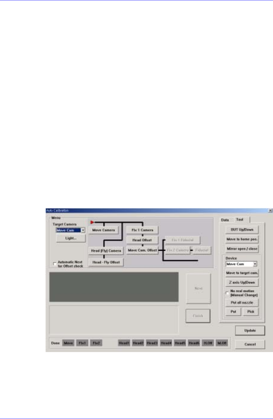
Machine Calibration 15-19 Select the items to calibrate. <Move Camera> button Calibrates the move camera (Fiducia l Came ra) in combination with the Calibration Plate. The Move Camera (Fiducial Camera) calibrat…
Samsung Component Placer CP45FV Administrator’s Guide
current coordinate of the device to be selected. Available devices are as follows;
Move Cam: Selects Teaching Camera.
Head1: Selects Head1.
Head2: Selects Head2.
Head3: Selects Head3.
Head4: Selects Head4.
Head5: Selects Head5.
Head6: Selects Head6.
Beam: Selects Beam.
<Move> button
Moves the head assembly by rotating the shafts of the X, Y, Z and R-axes driving
motors using the device selected from the <Device> combo box. At this time, the edit
box corresponding to the position to be read must be clicked on by a mouse.
<Get> button
Reads in the current position of the XY, Z, and R axes of the device selected in
<Device>.
<Fiducial Mark Default…> button
Activated only when the Fix Camera is used.
<Calibration> button
Performs the camera calibration function. When this button is clicked on, the
following screen is displayed.
<Target Camera> combo box
Select the camera to set light value.
<Light…> button
Set the light value for the selected camera.
<Menu> group
15-18

Machine Calibration
15-19
Select the items to calibrate.
<Move Camera> button
Calibrates the move camera (Fiducial Camera) in combination with the
Calibration Plate.
The Move Camera (Fiducial Camera) calibration procedure is as follows;
1. If a nozzle is mounted on the head, clear the select “No real motion” and
click on “Put all nozzle”. Perform calibration with a nozzle not mounted
on the head.
2. Click the <PCB In> button in the Board dialog box of the PCB Edit
menu tool bar and fix the Calibration Plate on the placement position.
3. Select the Camera [F9] in the SysSetup menu tool bar and execute the
Camera Setting dialog box.
4. Click the <Calibration> button in the Camera Setting dialog box to
display Auto Calibration dialogboxand click the <Move Camera> button
in the menu group.
5. If the “Prepare PCB for Calibration” message is displayed, click the
<Next> button since the calibration plate has been fixed on the
placement position.
6. If the message, “Move Head Assembly by jogbox. To adjust between
Fiducial move camera to Fiducial mark's center on the PCB” is
displayed, align the cross hair center of the camera screen with the plate
center and click the <Next> button.
7. The machine recognizes the black circle on the plate moving up and
down and left and right.
8. When the calibration is completed normally, the OLD data and New data
window are displayed. The data may be updated or canceled.
If an error occurs as a result of the outline of the black circle on the plate
not being clearly recognized during calibration, adjust the brightness of
the lighting so that the circle outline is clearly recognized. Then perform
the calibration again.
<Head[Fly] Camera> button
Calibrates the Fly Camera in combination with the Fly Camera Calibration
Tool.
The Fly Camera calibration procedure is as follows;
1. Remove the hex bolt in the area shown in the following figure.
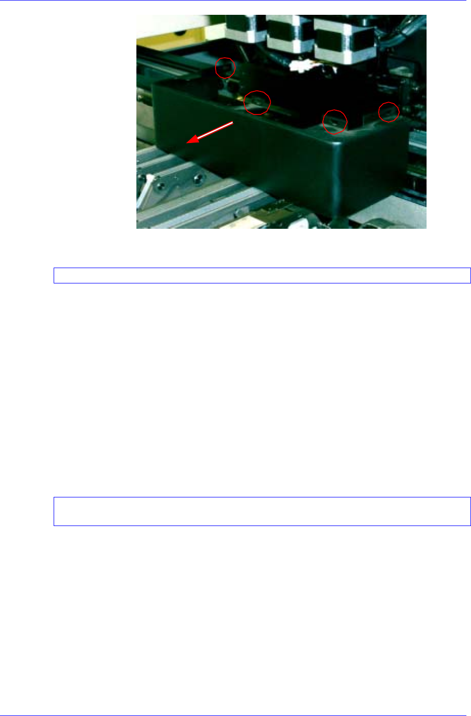
Samsung Component Placer CP45FV Administrator’s Guide
2. Remove the mirror cover in the area shown in the above figure.
When removing the cover, take care to ensure that it does not collide with the mirror.
3. If there is a nozzle on the head, click the <Put> button in the ANC dialog
box and place the nozzle on the pocket.
4. Select the Camera [F9] in the SysSetup menu tool bar and execute the
Camera Setting dialog box.
5. Click the <Calibration> button in the Camera Setting dialog box to
display the Auto Calibration dialog box and click the <Head [Fly]
Camera> button in the menu area.
6. If the message, “First, we must put all nozzles from heads manually. To
moving down Z axis, Click [Next].” is displayed, click the <Next>
button in the Auto Calibration dialog box.
7. If a message, “Next, Mirror will close. To close, Click [Next].” is
displayed, click the <Next> button in the Auto Calibration dialog box.
Since the mirror moves inward by about 45 degrees, take care not to cause any safety
related accidents.
8. If the message, “Setting the fly camera calibration tools on conveyor” is
displayed, install the calibration tool on the top surface of the conveyor
as shown below. Then click the <Next> button.
15-20