Administrator’s Guide(CP45FV) Eng.pdf - 第143页
Feeder Setup 8-1 1 coordinate of the device to be selected. Available devices are as follows; Move Cam: Selects teaching camera. Head1: Selects Head1. Head2: Selects Head2. Head3: Selects Head3. Head4: Selects Head4. Hea…
Samsung Component Placer CP45FV Series Administrator’s Guide
Dumps the corresponding component to the dump box.
<Close> button
Closes the dialog box.
<Feeder Move> button
Moves the cursor only to the grid area in which the feeder is mounted.
<Move Prev>
button
Moves the selected device to the slot on the first line with stick feeder installation
among the lines before the current line in the grid.
<Move Next>
button
Moves the selected device to the slot on the first line with stick feeder installation
among the lines after the current line in the grid.
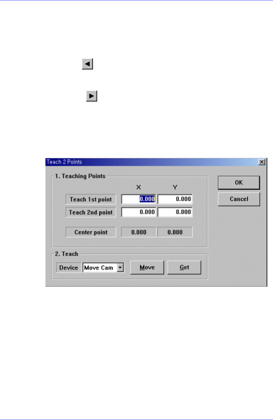
<2Pt. Teach…> button
When teaching stick feeder pickups point, the center point is calculated by teaching
two corner points at opposite angles of the pocket with the component. When this
button is clicked on, the following dialog box is displayed.
Figure 8-6. “Feeder : 2 point Teaching in the Stick Unit” dialog box
<1. Teaching Points> group
Set the positions of two corner points to find the center point.
Teach 1st point: Set the position of the first point.
Teach 2nd point: Set the position of the second point.
Center point: Finds and displays the center point from two corner points.
<2. Teach> group
Used to move the head assembly or spindle to the set position by rotating the
shafts of the X, Y-axes driving motors or to obtain the current shaft locations of
the X, Y-axes driving motors.
<Device> combo box
Used to select the corresponding device when moving the head assembly by
rotating the shafts of the X, Y-axes driving motors or to obtain the current
8-10

Feeder Setup
8-11
coordinate of the device to be selected. Available devices are as follows;
Move Cam: Selects teaching camera.
Head1: Selects Head1.
Head2: Selects Head2.
Head3: Selects Head3.
Head4: Selects Head4.
Head5: Selects Head5.
Head6: Selects Head6.
Beam: Selects Beam.
<Move> button
Moves the head assembly by rotating the shafts of the X, Y and Z-axes driving
motors using the device selected from the <Device> combo box. Before
executing “Move”, the edit box corresponding to the desired position must be
clicked on.
<Get> button
Reads in the current position of the XY axis of the device selected in <Device>.
Before executing “Get”, the edit box corresponding to the desired position must
be clicked on.
<OK> button
Sets the obtained center point as the new pickups point and closes the dialog box.
<Cancel> button
Ignores the obtained center point and closes the dialog box.
<Device> combo box
Selects the corresponding device to move the head assembly by rotating the driving
shafts of the X, Y-axes motors, move or rotate the spindle or obtain the current
coordinate of the device to be selected. Available devices are as follows;
Move Cam: Selects Teaching Camera.
Head1: Selects Head1.
Head2: Selects Head2.
Head3: Selects Head3.
Head4: Selects Head4.
Head5: Selects Head5.
Head6: Selects Head6.
Beam: Selects Beam.
<Move> button
Moves the head assembly by rotating the shafts of the X, Y-axes driving motors using
the device selected from the <Device> combo box. Before executing “Move”, the cell
in the grid corresponding to the desired position must be clicked on.
<Get> button
Reads in the current position of the XY axis of the device selected in <Device>.
Before executing “Get”, the cell in the grid corresponding to the desired position must
be clicked on.
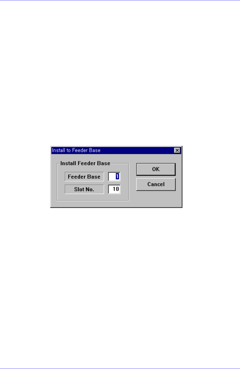
<Install to Feeder Base> group
Samsung Component Placer CP45FV Series Administrator’s Guide
When installing stick unit to the feeder base, set the feeder base unit and slot number
to install.
<Feeder Base>
Displays the feeder base where the corresponding stick unit is installed currently.
The numbers displayed are as follows.
0: Not installed on any feeder base.
1: Installed on Feeder Base(Front Feeder Base)1.
2: Installed on Feeder Base(Rear Feeder Base)2.
<Slot No.>
Displays the slot number of the feeder base where the corresponding stick unit is
installed currently. The numbers displayed are as follows.
0: Not installed in any slot.
1 - 52: Installed in the corresponding number slot.
<Change…> button
In the case of installing stick unit to the feeder base, change the feeder base unit
and slot number to install. When this button is clicked on, the following dialog
box is displayed.
<Install Feeder Base> group
Feeder Base
Displays the feeder base where the corresponding stick unit is installed
currently. The numbers displayed are as follows.
0: Not installed on any feeder base.
1: Installed on Feeder Base(Front Feeder Base)1.
2: Installed on Feeder Base(Rear Feeder Base)2.
Slot No.
Displays the slot number of the feeder base where the corresponding stick
unit is installed currently. The numbers displayed are as follows.
0: Not installed on any slot.
1 - 52: Installed in the corresponding number slot.
8-12