Administrator’s Guide(CP45FV) Eng.pdf - 第137页
Feeder Setup 8-5 <Move to Fix Camera> button It is activated only when the corresponding component is aligned by the vision camera and the align camera is the fix ca mera. When this bu tton is clicked…
Samsung Component Placer CP45FV Series Administrator’s Guide
Memo
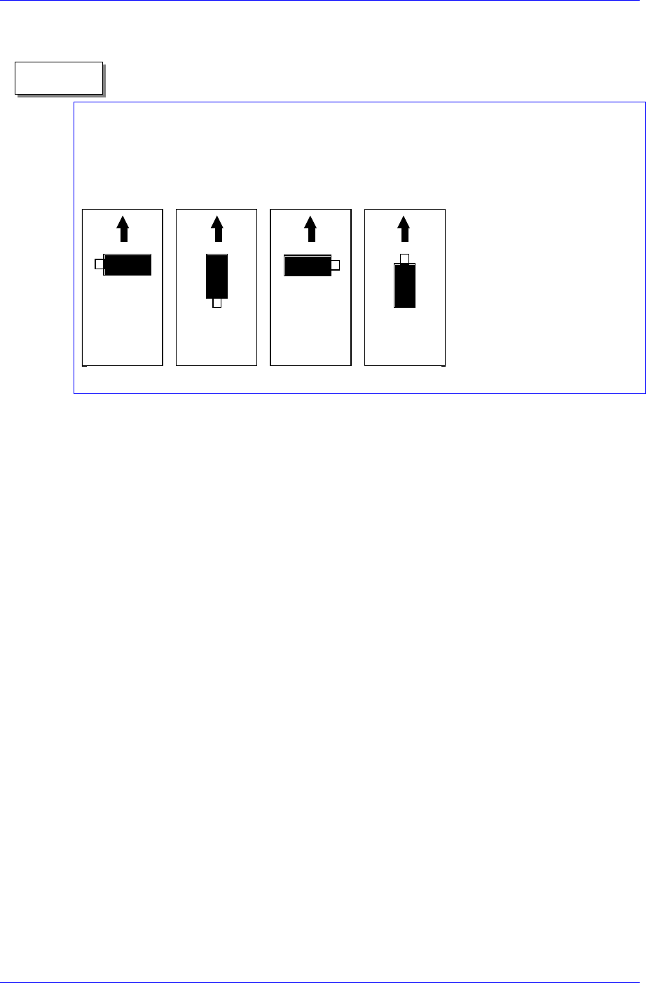
Definition on component supply angle and pickups angle
Supply angle (In the case of user):
The supply angle is based on the angle at which a component is supplied to the feeder. It
is the angle when the component is supplied from the feeder regardless of the feeder
being arranged in the front or at the rear.
0도 90도 180도 270도
0
°
90
°
180
°
270
°
<SK> column
When the tape feeder is installed in the corresponding slot, select whether to pick
up the component supplied from the tape feeder or not.
To pick it up leave the check box as it is, and check the check box not to pick it
up.
<Dump> column
When the tape feeder is installed in the corresponding slot, select the dump box
for the component supplied from the tape feeder. Available dump boxes are as
follows.
System Dump: the dump box installed in the system, it is installed in the front of
the conveyor of the machine.
User Dump: the dump box set in the system by the user. The location in the
system must be set.
<Pick> button
Executes component pickups from the tape feeder installed on the current row of the
grid. A device must be selected first. When pickups is successful, the following dialog
box is displayed.
8-4

Feeder Setup
8-5
<Move to Fix Camera> button
It is activated only when the corresponding component is aligned by the vision
camera and the align camera is the fix camera. When this button is clicked on,
the head block is moved to the fix camera..
<Part Align> button
Executes alignment of the corresponding component.
<Dump> button
Dumps the corresponding component to the dump box.
<Close> button
Closes the dialog box.
<Edit Part Info> button
Shows the Part Edit dialog for the corresponding component.
<Slot Move> button
Select whether to move the selected device by slot or by slot with tape feeder
installation. Whenever this button is clicked on, “Slot Move” and “Feeder Move”
alternates.
<Move Prev>
button
If <Slot Move> is set to “Slot Move”, moves the selected device to the slot on the
previous line of the current line in the grid.
If <Slot Move> is set to “Feeder Move”, moves the selected device to the slot on the
first line with tape feeder installation among the lines before the current line in the
grid.
<Move Next>
button
If <Slot Move> is set to “Slot Move”, moves the selected device to the slot on the
next line of the current line in the grid.
If <Slot Move> is set to “Feeder Move”, moves the selected device to the slot on the
first line with tape feeder installation among the lines after the current line in the grid.
<Pusher U/D> button
Moves up or down the air pressure cylinder in the slot on the current line in the grid.
When the feeder driving cylinder is on, the driving lever of the feeder is lifted, and
the shutter at the top of the feeder opens. Pickups point teaching is executed in this
state.
Samsung Component Placer CP45FV Series Administrator’s Guide
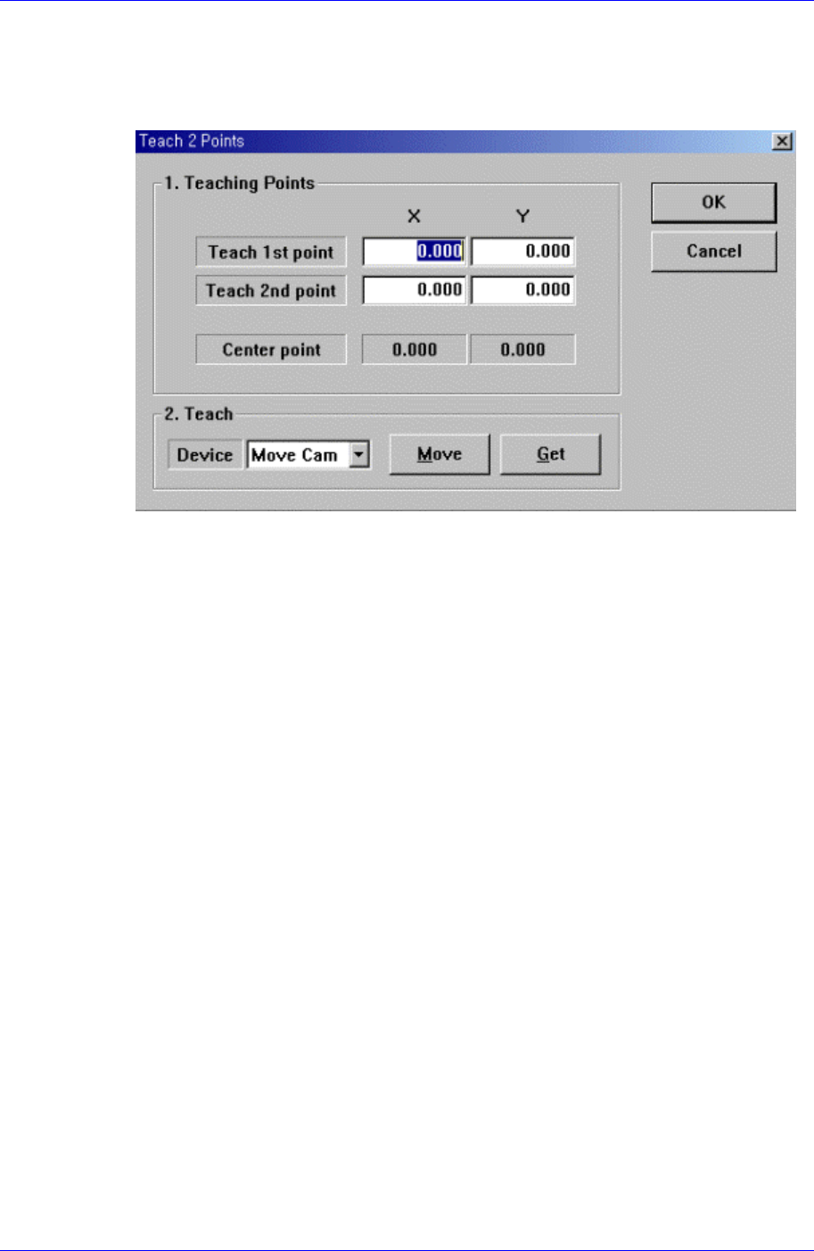
<2Pt. Teach…> button
When teaching the tape feeder pickups point, finds the center point by teaching two
corner points at opposite angles of the pocket containing the component. When this
button is clicked on, the following dialog box is displayed.
Figure 8-4. “Feeder :2 point teaching in the Feeder Base” dialog box
<1. Teaching Points> group
Set the position of two corner points to find the center point.
Teach 1st point: Set the first point.
Teach 2nd point: Set the second point.
Center point: Finds the center point from the two corner points and displays it.
<2. Teach> group
Used to move the head assembly to the designated position by rotating the
driving shaft of the X and Y-axes motors or obtain the current position of the
shafts of the X and Y-axes motors.
<Device> combo box:
Selects the corresponding device to move the head assembly by rotating the
driving shafts of the X and Y motors or obtains the current coordinate of the
device to be selected. Available devices are as follows;
Move Cam: Selects Teaching camera.
Head1: Selects Head1.
Head2: Selects Head2.
Head3: Selects Head3.
Head4: Selects Head4.
Head5: Selects Head5.
Head6: Selects Head6.
Beam: Selects Beam.
<Move> button:
Moves the head assembly by rotating the shafts of the X, Y-axes driving
motors using the device selected from the <Device> combo box. “Move”, the
8-6