Administrator’s Guide(CP45FV) Eng.pdf - 第230页
Samsung Component Placer CP45FV Administrator ’ s Guide If the standard genuine nozzle is not used, vacuum is not created properly so that the component may not be picked up. Therefore, a standard genuine n…
Placement Test
14-15
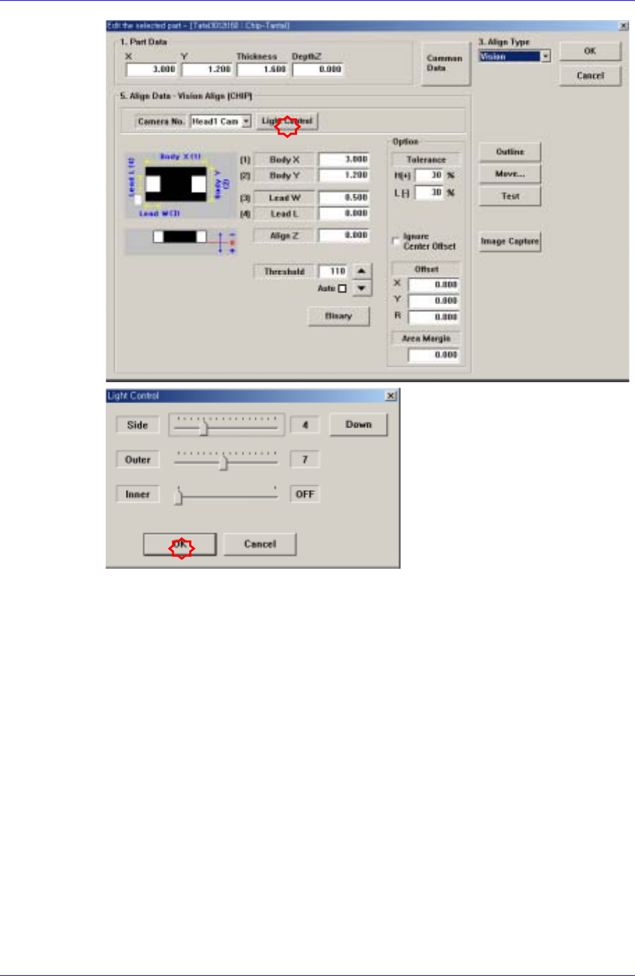
Click the <OK> button to apply the changed lighting value to the corresponding
component profile, and click the <Part Align> button to perform component
recognition again.
If the component is still not recognized, click the <Edit Part Info> button again to
change the Align Data for the corresponding component.
For more details concerning the component profile change, refer to the “7.1 Part
[F3](page 7-1)”.
Once the component profile is changed, click the <OK> button in the “Edit the
selected part” dialog box to apply the change, and click the <Part Align> button to
perform component recognition again.
14.3.5. Component Placement Error
Occurs in the following cases; the nozzle has a defect; the component placement height
setup is incorrect; the air blow or vacuum function is not working properly; and the
placement related parameter setup is inappropriate.
When the nozzle has defect
Error occurs if a standard genuine nozzle is not used or the nozzle is clogged with
foreign matter or the nozzle suitable to the component is not used.
Samsung Component Placer CP45FV Administrator’s Guide
If the standard genuine nozzle is not used, vacuum is not created properly so that
the component may not be picked up. Therefore, a standard genuine nozzle must
be used.
When the nozzle is clogged, clean the nozzle referring to the “2.1 Nozzle” of the
Maintenance Reference.
Use the nozzle suitable to the component.
When the component placement height setup is incorrect.
The component thickness is set incorrectly in the component profile.
The Backup Pin position setup is inappropriate or there is a problem with the
flatness of the PCB due to improper clamping.
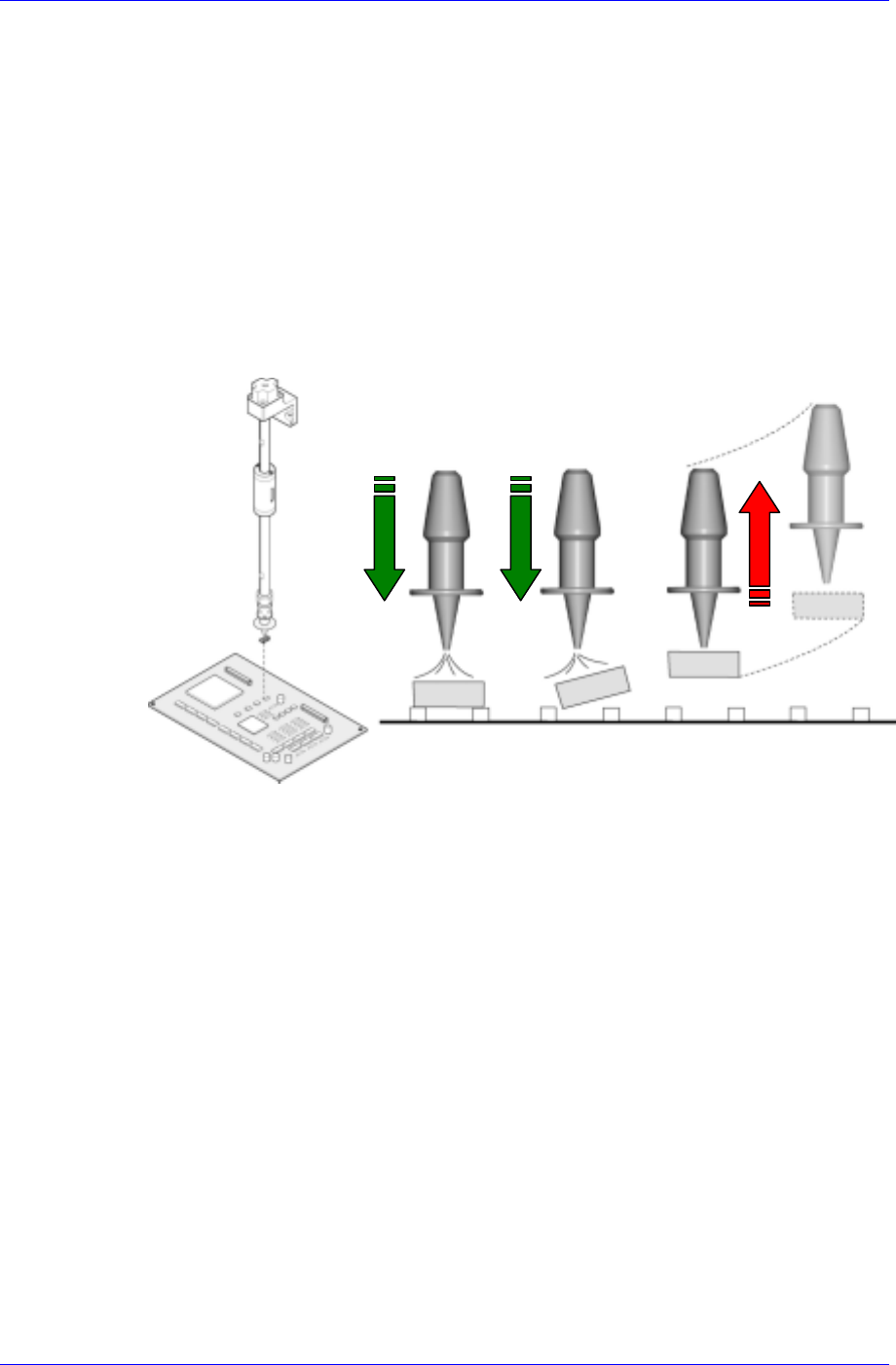
When the air blow or vacuum function is not working properly and the placement
related parameter setup is inappropriate.
A B C
Case A: Air blow is setup normally. The air volume and the delay are accurate.
Case B: The air volume is too much or the delay is too long.
Case C: The air volume is too small or the delay is too short. In such case, the
placement error occurred due to the component being lifted up to the nozzle tip
prior to placement of the component.
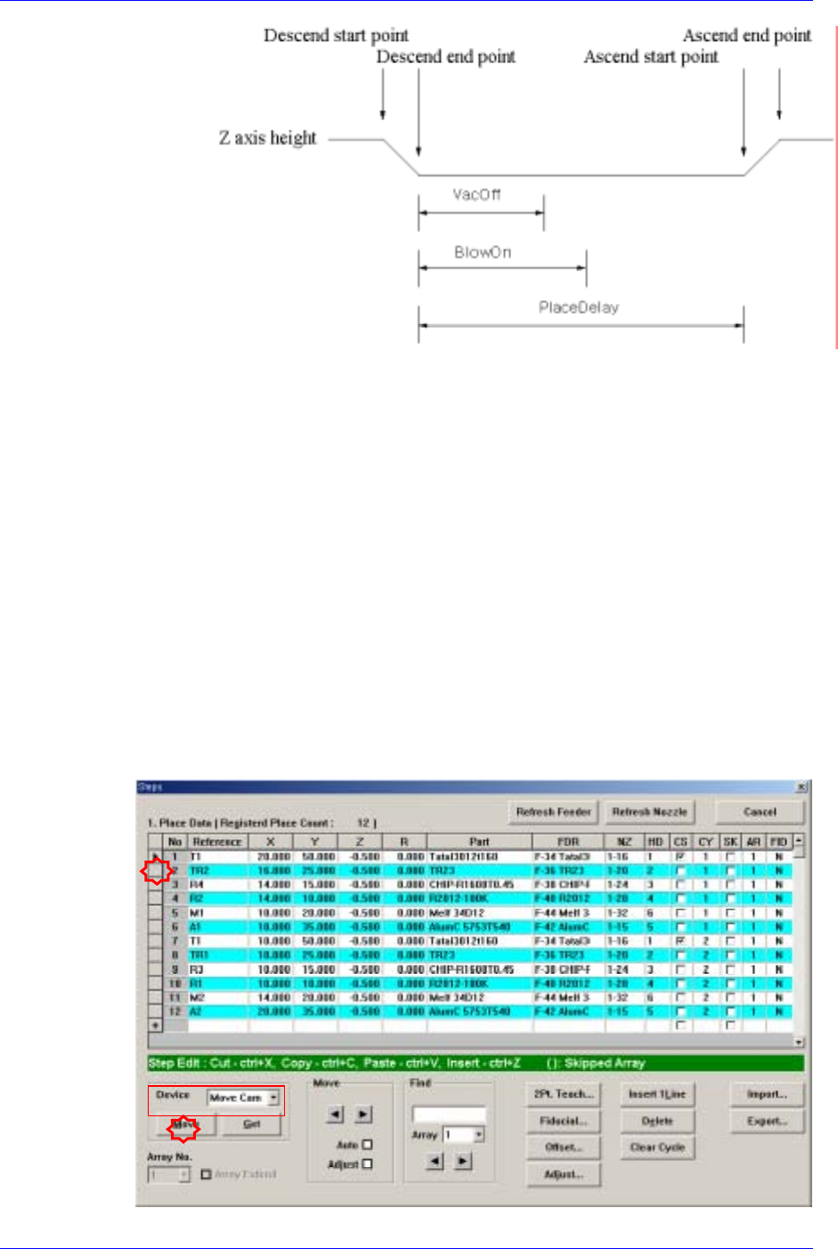
The following figure shows the setup of the air blow and vacuum for component
placement.
14-16
Placement Test
14-17
Please refer to “Figure 7-6 (Page 7-6)" .
14.4. Position Correction
After the placement test, any error related to the placement position shall be solved
through position calibration.
14.4.1. Specific Placement Point Position Error
Even though the components were placed on the PCB normally, placement position error
may occur at one specific point and it may have been caused by the incorrect coordinate
of the corresponding position.
Checking position on the PCB
Move the “Move Camera” to the actual position on the PCB corresponding to the
coordinate of the placement point where placement position error has occurred, and
check the placement position through the vision monitor.