Administrator’s Guide(CP45FV) Eng.pdf - 第275页
System Setup 16-9 Set the offset value between the m ach ine origin and the PCB board origin. <PCB Stop Point> edit box Set the PCB board origin. The method to setup the PCB Stop Origin is as follows; 1. Align th…
Samsung Component Placer CP45FV Administrator’ Guide
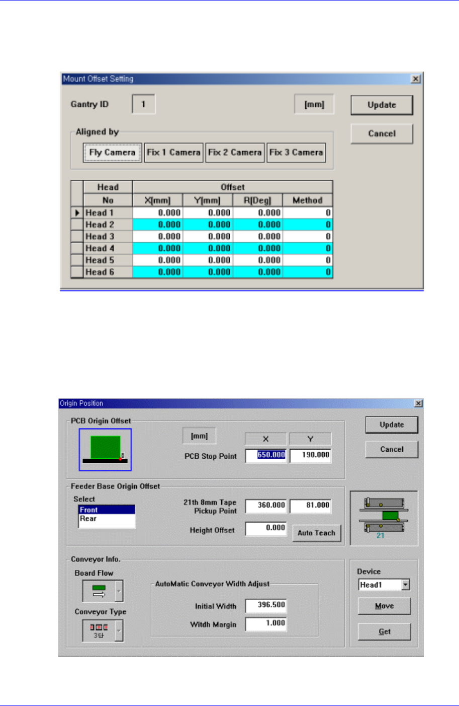
16.3. Mount Offset [F5]
Sets the Mount Offset value of the machine.
When this button is clicked on, the following dialog box is displayed.
Figure 16-5. “Sys. Setup : Mount Offset Setting” dialog box
16.4. Origin [F5]
Sets the origin of each factor. When this button is clicked on, the following dialog box is
displayed.
Figure 16-6. “Sys. Setup : Origin Position” dialog box
<PCB Origin Offset> group
16-8
System Setup
16-9
Set the offset value between the machine origin and the PCB board origin.
<PCB Stop Point> edit box
Set the PCB board origin.
The method to setup the PCB Stop Origin is as follows;
1. Align the conveyor width and click the <PCB In> button to place the
calibration plate on the conveyor.
The PCB that is completely rectangular may be used instead of the
calibration plate.
2. Execute the Origin Position dialog box in the System Setup menu.
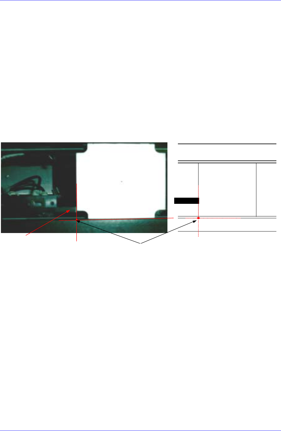
3. In order to shift the Move Camera to the position in the following figure,
select the <PCB Stop Point> edit box first with the mouse and click the
<Move> button after selecting the “MoveCam” in the <Device> combo box.
- 1 -
Stopper
Vision
Plate
Stopper
Vision
Plate
Teaching
Point
Conveyor후면
Conveyor전면
4. Move the head using the teaching box to align the teaching point with the
cross hair center of the Move Camera (Fiducial Camera).
Since the conveyor belt is seen from the gap between the conveyor and the
calibration plate, the surface where the conveyor and the calibration plate
contact appears as two lines as shown in the above figure. Perform teaching
accurately keeping this in mind.
5. Select the <PCB Stop Point> edit box using the mouse and click the <Get>
button to enter the coordinate of the current position in the <PCB Stop
Point> edit box.
6. Once the normal procedure is completed, click the <Update> button to apply
the changed value.
<Feeder Base Origin Offset> group
Set the data on feeder base.
<Select> list box
Select the front or rear feeder base.
<21th 8mm Tape Pickup Point> edit box
To set the feeder base origin, install a 8mm tape feeder in the 21st slot of each
feeder base and set the feeder base origin by using the pickups point of this
Samsung Component Placer CP45FV Administrator’ Guide
feeder.
The method to set the Feeder Base Origin is as follows;
1. Mount the smallest components on the feeder and install them in the 21
st
slot
of the front feeder base.
Before installing the feeder, check if there are any components remaining on
the feeder base and remove them.
2. Select “MoveCam” in the <Device> combo box and click the <Move> button.
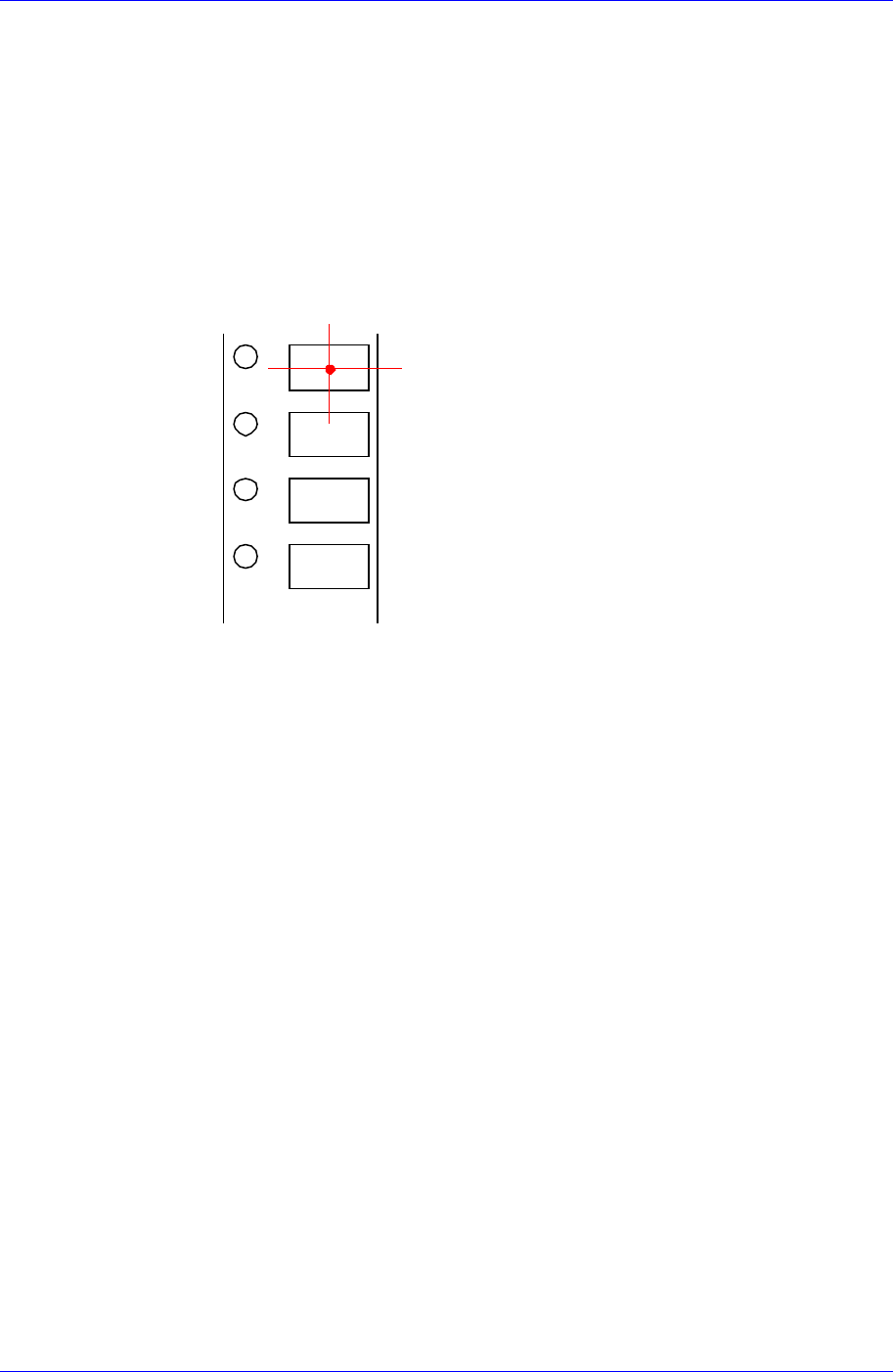
3. Teach the center using the Move Camera (Fiducial Camera) as shown in the
following figure. At this time, teach the pocket center rather than the
component center.
4. Align the cross hair center of the Move Camera (Fiducial Camera) shown on
the vision monitor on the pocket center using the teaching box. Then select
the <21th 8mm Tape Pickup Point> edit box using the mouse and click the
<Get> button to enter the current coordinate in the <21th 8mm Tape Pickup
Point> edit box.
5. Select “Rear” in the <Select> list box and then install the feeder in the 21
st
slot of the feeder base and perform teaching.
<Height Offset> edit box
Set the Z value of the feeder base origin.
<Conveyor Info.> group
Set the data on conveyor.
<Board Flow> combo box
Displays the direction of conveyor movement. To change the direction of
conveyor movement, please contact this machine manufacturer.
<Conveyor Type> combo box
Displays the type of the conveyor. To change the type of the conveyor, please
contact this machine manufacturer.
<AutoMatic Conveyor Width Adjust> group
The method to set up the Conveyor Width Origin is as follows;
1. Perform conveyor homing using the teaching box as shown in the following
figure.
16-10