Administrator’s Guide(CP45FV) Eng.pdf - 第169页
Optimization 10-3 displayed here. Point column Displays the number of placement points for each component. You can refer to it when you decide the number of feeders to arrange. ARG column Displays the number …
Samsung Component Placer CP45FV Series Administrator’s Guide
10.2. Setup Menu/Tape Feeder
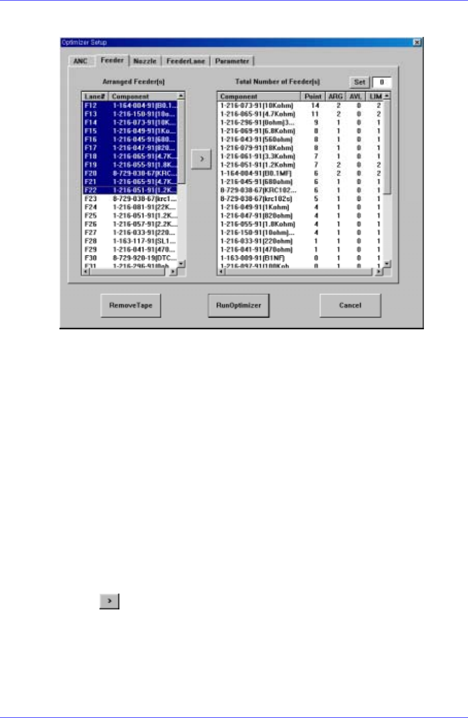
Figure 10-2. "Optimizer Setup: Tape Feeder" dialog box
The screen to set the optimum arrangement of tape feeder. The Optimizer can arrange
tape feeders in the optimum feeder lanes by considering simultaneous pickup and
operation time. But the user must specify the installation position for tray feeders and
stick feeders.
<Arranged Feeder(s)> list box
Lane# column
In the left list box, the number of the feeder that is already arranged in the feeder
lane and each component name are displayed. For the front feeder base, F is
attached in front of the feeder lane number and for the rear feeder base, R is
attached in front of the feeder lane number.
Componentcolumn
The feeders listed here are not arranged arbitrarily by the Optimizer. However,
the feeders already arranged affect other feeders when they are arranged by the
Optimizer. That is, when there are feeders already arranged, new feeders are
arranged to increase simultaneous pickup.
Among the feeders displayed here, move the feeders for which you want optimal
arrangement by the Optimizer to the right list box by clicking on the arrow button
(
) and execute the Optimizer.
<Total Number of Feeder(s)> list box
In the right list box, the number of placement points for each component, the number
of arranged tape feeders and the number of feeders to be arranged are displayed.
Component column
Of the components used by the PCB being edited, tape feeder components are
10-2

Optimization
10-3
displayed here.
Point column
Displays the number of placement points for each component. You can refer to it
when you decide the number of feeders to arrange.
ARG column
Displays the number of feeders already arranged on the feeder lane for each
component. This number is the same with the number of feeder lanes in the left
list box.
AVL column
Displays the number of feeders to be arranged by the Optimizer for each
component.
LIM column
Displays the sum of the feeders displayed in the <ARG> and <AVL> columns
for each component. In other words, it is the limit number of feeders that can be
assigned to each component. The minimum value is 1.
<Set> button
Used to specify the number of feeders to be used for each component. If 1 feeder is
arranged for a component, entering 3 in this box and pressing the limit button makes
the number in the AVL column to 2. The Optimizer arranges up to 2 new feeders. Set
an appropriate number of feeders while considering the number of placement points
for each component. To get a better operation efficiency, allocate more feeders for the
components that have many placement points.
Arrow button (
)
Used to change the setting of an arranged feeder to the setting of a feeder to be
rearranged by the Optimizer.
<RemoveTape> button
Click on the <Remove Button> to ignore all the tape feeders already arranged and to
arrange new tape feeders. As this button is present at the bottom of the Optimizer
setting screen, it can be selected although the tape feeder setting tap is not displayed.
Samsung Component Placer CP45FV Series Administrator’s Guide
10.3. Setup Menu/Nozzle
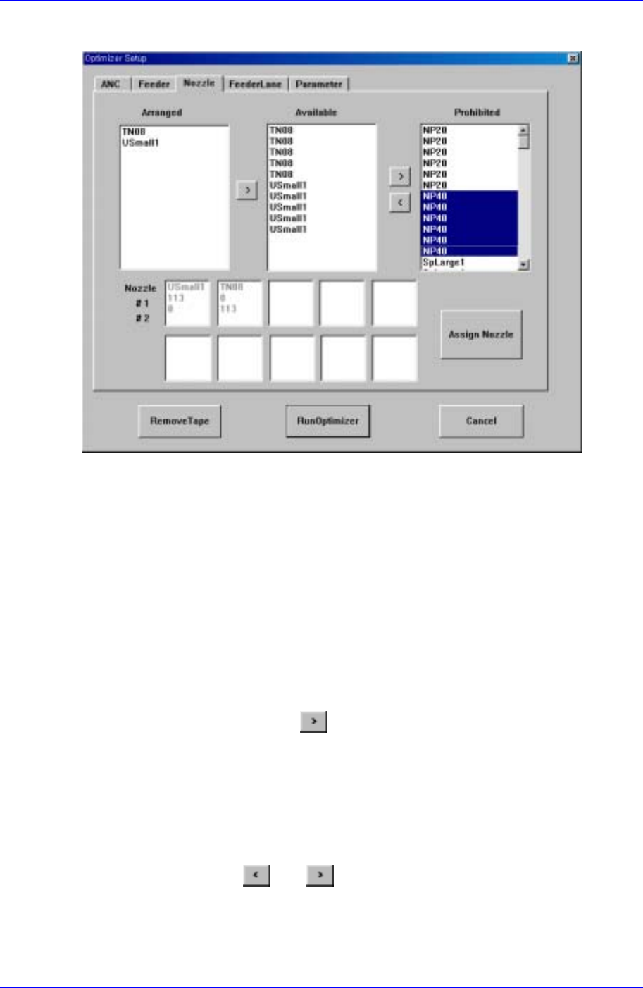
Figure 10-3. "Optimizer Setup: Nozzle" dialog box
The screen to set the optimum arrangement of nozzles.
All the nozzles registered in the equipment are displayed in the <Arranged>, <Available>,
or <Prohibited> list box. The sum of nozzles in each list box is the same with the sum of
the heads (in the case of CP45F/V, it is 6). The user can set a desired number of nozzles to
be arranged by the Optimizer by adjusting the number of nozzles in the <Available> list
box.
<Arranged> list box
The user can arrange nozzles in the ANC pocket directly in the ANC Setup Dialog
Box. The nozzles arranged in advance are displayed in the <Arranged> list box. The
nozzles listed here are used for operation but the Optimizer does not arrange them in
the pocket arbitrarily. To rearrange the nozzles already arranged by using the
Optimizer, select the desired nozzle and move it to the <Available> list box by
clicking on the arrow button (
). If the user wants to arrange the nozzle directly
again, the user needs to display the ANC Setup Dialog box and specify the pocket.
<Available> list box
The list box to specify the nozzles to be arranged in the pocket by the Optimizer.
When the Optimizer is executed, NP20 nozzle arranges in the empty nozzle pockets.
The number of nozzles to be arranged by the Optimizer can be increased and
decreased between the <Available> list box and the <Prohibited> list box by clicking
on the arrow buttons
and ..
<Prohibited> list box
This list box works like a buffer for unnecessary nozzles. The nozzles that do not
need to be rearranged can be placed in the <Prohibited> list box.
10-4