Administrator’s Guide(CP45FV) Eng.pdf - 第172页
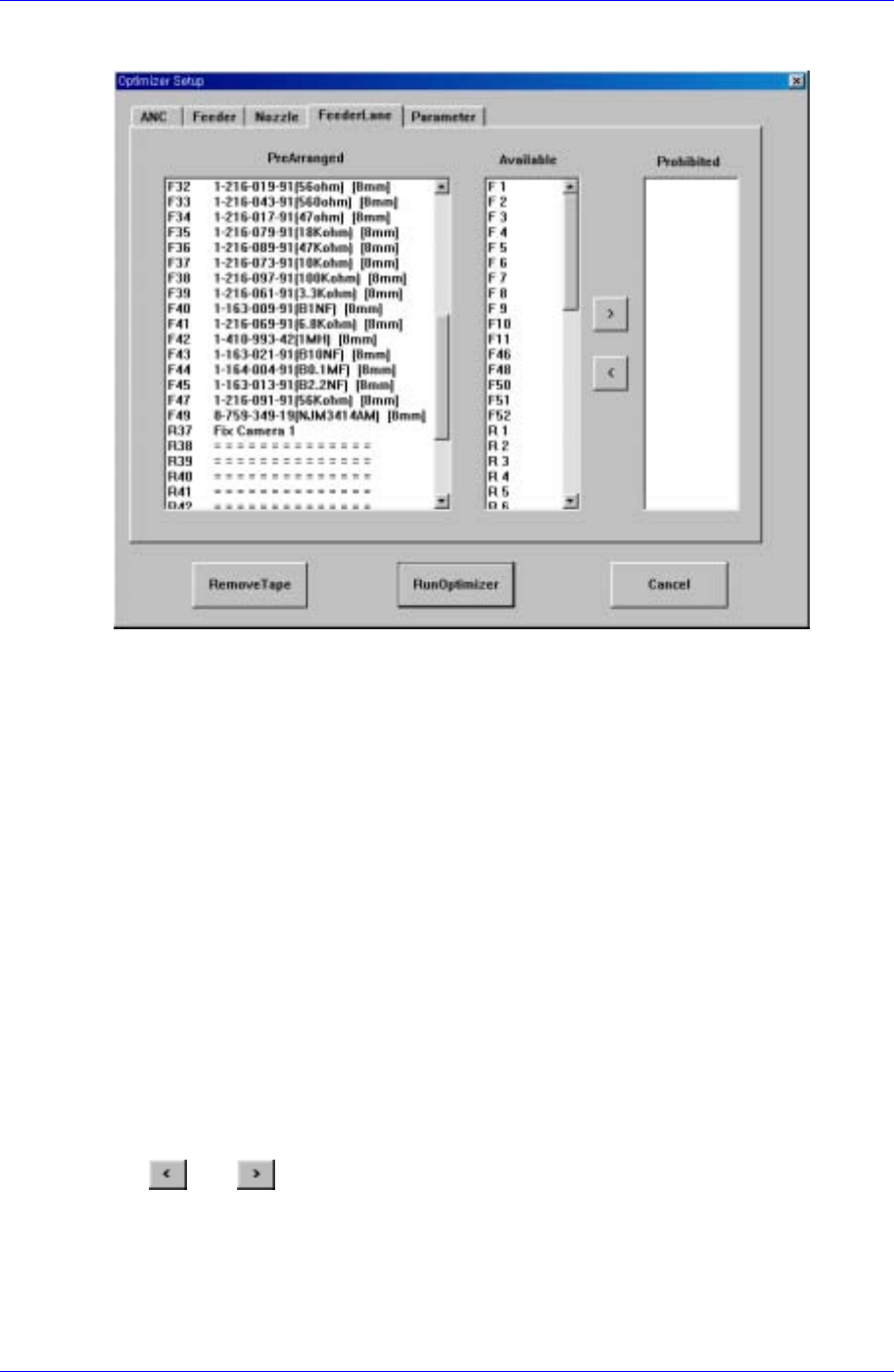
Samsung Component Placer CP45FV Series Administrator ’ s Guide 10.4. Setup Menu/Feeder Lane Figur e 10-5. "Optimizer Setup: Feeder Lane" dialog box The screen to set the feeder lane to be used for feeder arrang…
Optimization
10-5
<Nozzle #1 #2> list box
All the nozzles used for the PCB being edited are displayed in this list box and the
status of each nozzle being the first operation nozzle or the second operation nozzle
for the component is displayed at the same time. #1 indicates the sum of placement
points of the component assigned to the first operation nozzle and #2 the sum of
placement points of the component assigned to the second nozzle.
<Assign Nozzle> button
Used to assign applicable heads for each nozzle separately. When this button is
clicked on, the following dialog box is displayed.
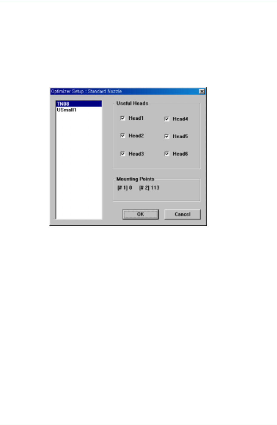
Figure 10-4. "Optimizer Setup: Standard Nozzle" dialog box
Basically all nozzle types can be applied to any head, therefore all heads are checked.
But there are occasions when a certain nozzle has to be operated in a certain head.
Also, this can be used when the user wants to assign a certain head to a certain nozzle.
The above figure shows the nozzle TN14 can operate on any head between Head1
and Head6.
<Useful Heads> check box group
The heads that can be used by the selected nozzle type. As a standard, check so that
Head1, Head2, Head3, Head4, Head5, and Head6 can be used.
<Mounting Points> group
This group shows the number of components used by the nozzle selected for the
current PCB. This can be used as a reference data when the user assigns the
applicable heads to each nozzle. #1 shows the total number of placement points of the
component for which #1 nozzle is selected and #2 shows the total number of
placement points of the component for which #2 nozzle is selected.
Figure 10-4 shows that TN04 is selected for 1# nozzle of four components and for 2#
nozzle of two components.
<OK> button
Saves the selected options and closes the dialog box.
<Cancel> button
Cancels the selected options and closes the dialog box.
Samsung Component Placer CP45FV Series Administrator’s Guide
10.4. Setup Menu/Feeder Lane
Figure 10-5. "Optimizer Setup: Feeder Lane" dialog box
The screen to set the feeder lane to be used for feeder arrangement by the Optimizer. The
devices that can be arranged on the feeder lane are tape feeders, stick feeder units,
movable ANCs, camera units fixed on the feeder lane. This screen shows the current
arrangement status on each feeder lane. The feeder lanes on which devices shouldn't be
arranged in the Optimizer can be specified.
<PreArranged> list box
Displays the status of already installed feeder lanes, installed tape feeders, movable
ANCs, and cameras. The F in the feeder lane number indicates the front feeder base,
R indicates the rear feeder base.
<Available> list box
Displays the feeder lanes on which the Optimizer can arrange tape feeders.
<Prohibited> list box
Specify the feeder lanes on which you don't want to arrange any feeder unit, ANC, or
camera, so that they are displayed in this group. No device is arranged by the
Optimizer on the feeder lanes listed here. But you don't need to specify each lane in
the <Prohibited> list box while considering the width of the feeder unit, ANC, and
camera unit. The Optimizer is set to consider the width of the device to be arranged
on the feeder lane so that there is no mechanical interference. Use the arrow buttons,
and to move between the <Available> list box and the <Prohibited> list
box.
10-6
Optimization
10-7
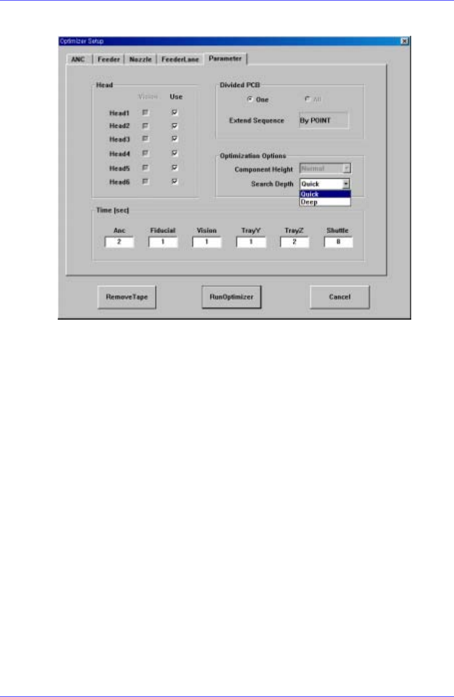
10.5. Setup Menu/Parameters
Figure 10-6. "Optimizer Setup: Parameters" dialog box
Lastly, the screen to set the options and parameters for the Optimizer execution.
<Head> check box group
components. Check the vision check box when the vision arranged components in the
corresponding head are to be operated. For full vision equipment like CP45F/V NEO
model, check all the vision check boxes. The use check box indicates whether to use
the corresponding head. For example, if there is a problem with Head3 and it is
difficult to operate, click on the use check box for Head3 and leave it blank. Then the
Optimizer creates an operation program without using the prohibited head. When all
the heads are prohibited, an error message is displayed immediately when the
Optimizer is executed.
<Divided PCB> box group
Used to specify optimization options and display method of the MMI step program
when the Array PCB is edited. The Array PCB can have only one unit PCB displayed
in the step program and have the same operation repeated for each PCB or have the
step program for the whole PCBs be displayed. This can be selected in the step edit
screen of the MMI. When the former is selected, it is indicated in the <One> button in
the <Divided PCB> box, and the latter is indicated in the <All> button.
The <Extended Sequence> combo box in the <Divided PCB> box is activated only
when <All> is selected. Optimization method for Array PCBs in the Optimizer is
decided here. When <By PCB> is selected, the Optimizer creates a step program so
that an optimization program for a unit PCB is created and applied to other PCBs in
sequence. On the other hand, when <By Point> is selected, all PCBs are considered
as one and an optimization program for all placement points is created. For example,
in the case of an array PCB consisting of 4 PCBs, the <By PCB> option completes an
operation for a PCB and then starts an operation for the next PCB, while the <By