Administrator’s Guide(CP45FV) Eng.pdf - 第107页
Part Registration 7-23 <Size> group Set the align size. <T otal Y> edit box Displays the size of the whole component in Y direction. It is calculated and displayed when <Body Y> and <Lead Le …
Samsung Component Placer CP45FV Series Administrator’s Guide
data.
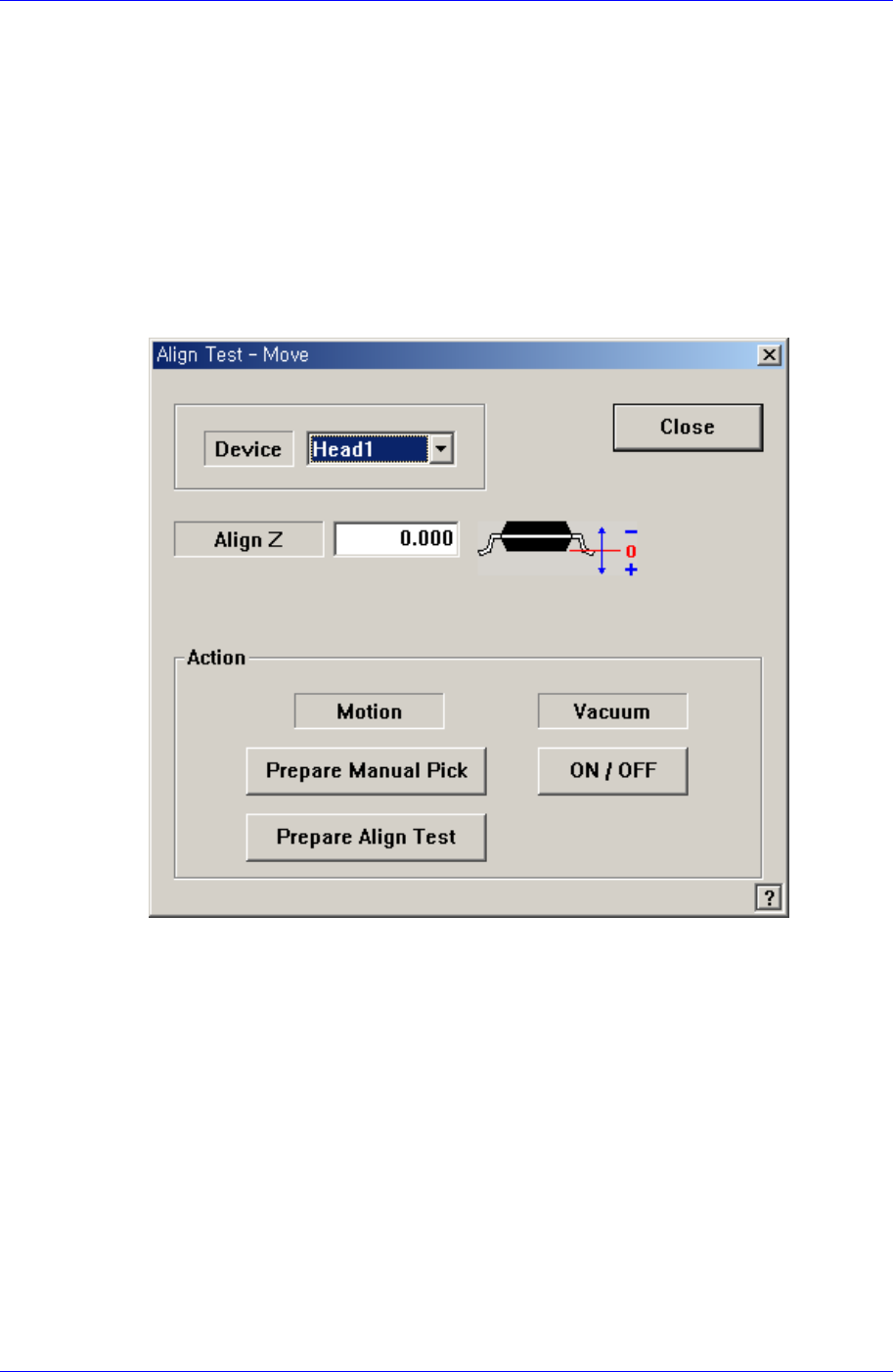
<Move…> button
Performs component pickups or moves to the stage camera. Please refer to “7.2.1.1
Common Align Data (Page 7-9)” for more information.
<Test> button
Tests component recognition by using the set align data. Please refer to “7.2.1.1
Common Align Data (Page 7-9)” for more information.
<Image Capture> button
Helps to specify the optimum lighting value. The lighting is gradually changed
automatically and the images are saved. The user can check the best image and
identify the optimum lighting value.
Please refer to “7.2.1.1 Common Align Data (Page 7-9)” for more information.
7.2.6. Hemt component data setting
Set the align data for Hemt components.
Please refer to “Setting User IC component data”.
7.3. IC component data setting
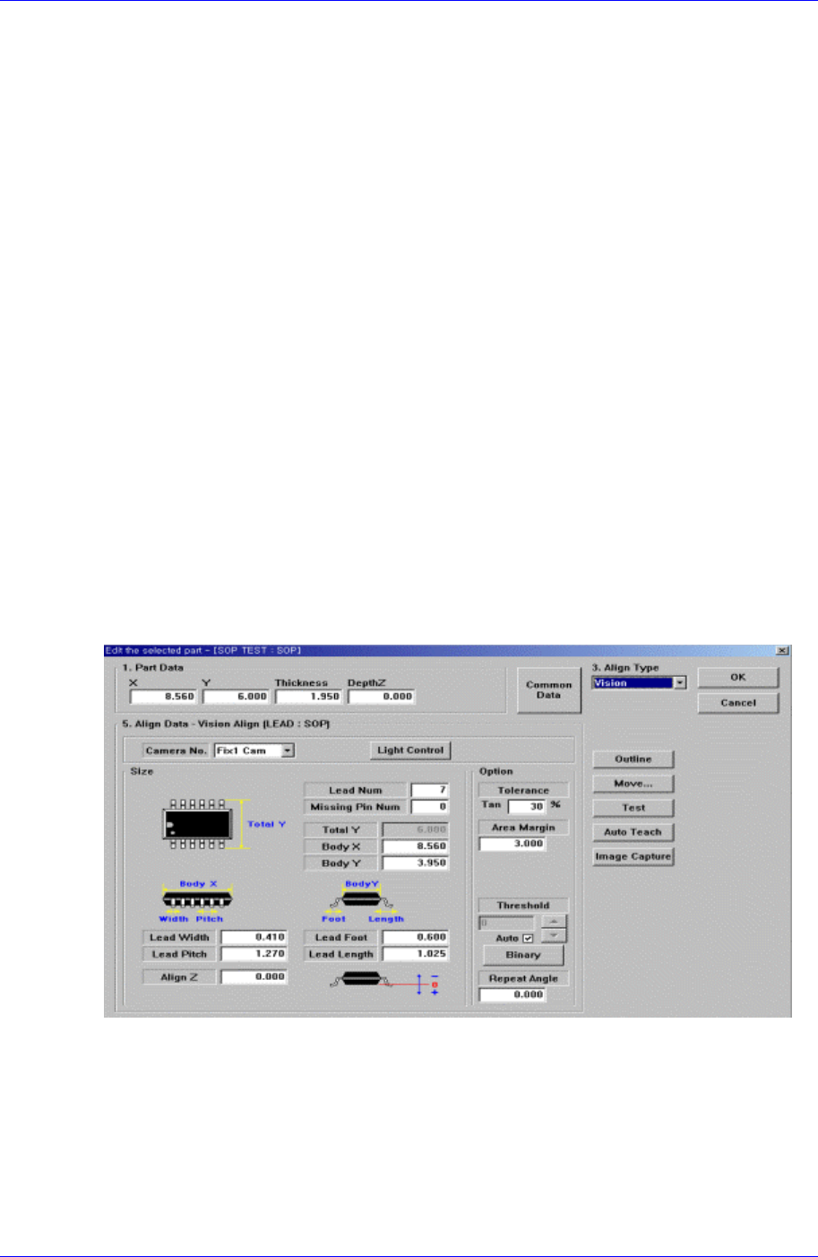
7.3.1. SOP component data setting
Set the align data for SOP components.
Figure 7-15. “Align Type = Vision, Package Group = SOP” dialog box
<Camera No.> combo box
Select the camera to recognize the component. Please refer to “7.2.1.1 Common Align
Data (Page 7-9)” for more information.
<Light Control> button
Select the light for the camera to recognize the component. Please refer to “7.2.1.1
Common Align Data (Page 7-9)” for more information.
7-22
Part Registration
7-23
<Size> group
Set the align size.
<Total Y> edit box
Displays the size of the whole component in Y direction. It is calculated and
displayed when <Body Y> and <Lead Length> are determined. ( <Body Y> +
<Lead Length> * 2)
<Outline> button
Displays the outline of the component by using the set align data.
<Move…> button
Performs component pickups or moves to the stage camera.
Please refer to “7.2.1.1 Common Align Data (Page 7-9)” for more information.
<Test> button
Tests component recognition by using the set align data. Please refer to “7.2.1.1
Common Align Data (Page 7-9)” for more information.
<Image Capture> button
Helps to specify the optimum lighting value. The lighting is gradually changed
automatically and the images are saved. The user can check the best image and
identify the optimum lighting value.
Please refer to “7.2.1.1 Common Align Data (Page 7-9)” for more information.
7.3.1.1. Common Align Data
The following items are common to IC component.
<Lead Num> edit box

Samsung Component Placer CP45FV Series Administrator’s Guide
Set the number of leads on a side.
<Missing Pin Num> edit box
Set the number of empty leads at the center of the lead column(group).
<Body X> edit box
Set the size of component body in X..
<Body Y> edit box
Set the size of component body in Y.
<Lead Width> edit box
Set the width of lead.
<Lead Pitch> edit box
Set the lead pitch
<Lead Foot> edit box
Set the length of the lead that touches the surface.
<Lead Length> edit box
Set the length of the lead viewed in the Align Camera.
<Align Z> edit box
Set the height for recognition. Based on the component surface, if the top is to be
recognized, set - value and if the bottom is to be recognized, set + value.
<Option> group
Set the align option data.
<Area Margin> edit box
Set the limit for the image to be off the center of the screen when the component
is recognized. For example, if this value is 5mm, the component image should be
within 5mm of the center of the screen.
<Tolerance Tangential> edit box
Set the allowance tolerance when the lead is pushed to the side. Set it as a
percentage of <Lead Pitch>.
<Threshold> edit box
When there is a pre-treatment process for component recognition and the gray
level image is converted into binary, it is the value used as the criteria to
determine black and white.
The value range is 0 – 255(0: black, 255: white), and this value serves to
differentiate the component from the background. When the set value is 0, the
value is set automatically during component recognition.
<Auto> check box
Check it to set the <Threshold> value automatically.
<Binary> button
Displays the binary image of the component on the Vision Monitor screen.
<Repeat Angle> edit box
In the case of the work needed for high precision, this re-recognizes and pick-up
and placement of the component by performing correction according to the
vision recognition result. For example, if o.i is inputted for the repeat angle, it
corrects the angle after vision recognition and re-recognizes it. If the result of re-
7-24