Administrator’s Guide(CP45FV) Eng.pdf - 第248页
Samsung Component Placer CP45FV Administrator ’ s Guide fourth (third) scale of the vision monitor. When using the FO V 15mm F ly Camer a When using the FOV 15mm Fly Camera, align the LED bottom line with the fourth (thi…
Machine Calibration
15-9
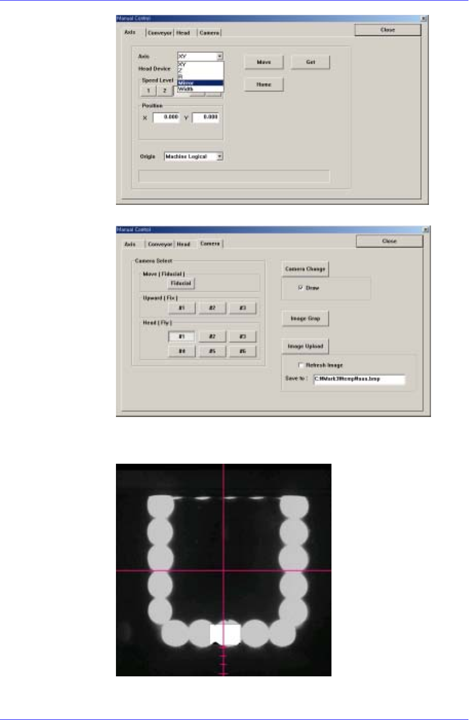
4. Select the Camera corresponding to the head in the Camera Tab dialog box.
5. Move the mirror axis using the teaching box so that the bottom center of the
LED of the corresponding camera falls on the fourth scale from the bottom
of the cross hair on the vision monitor.
When using the FOV
25mm Fly Camera
When using the FOV 25mm Fly Camera, align the LED bottom line with the
Samsung Component Placer CP45FV Administrator’s Guide
fourth (third) scale of the vision monitor.
When using the FOV
15mm Fly Camera
When using the FOV 15mm Fly Camera, align the LED bottom line with the
fourth (third) scale of the vision monitor.
6. Close the Manual Tools dialog box.
7. At this time, apply the Mirror value in the “Position” dialog box as the Mirror
value of the Check Position.
Z-axis Height Teaching (Head Z Teaching)
The default value is 46 for the CP45FV and 48 for the CP45FV NEO.
1. Select the Current Position in the View menu and execute the “Position”
dialog box.
2. Click the <Manual Tools> button in the Nozzle Check Setting Tab dialog
box and execute the “Manual Control” dialog box.
3. Select the Z in the <Axis> combo box of the Axis Tab dialog box.
4. Select the Camera in the Camera Tab dialog box, which corresponds to the
head for which whether the nozzle is mounted is checked.
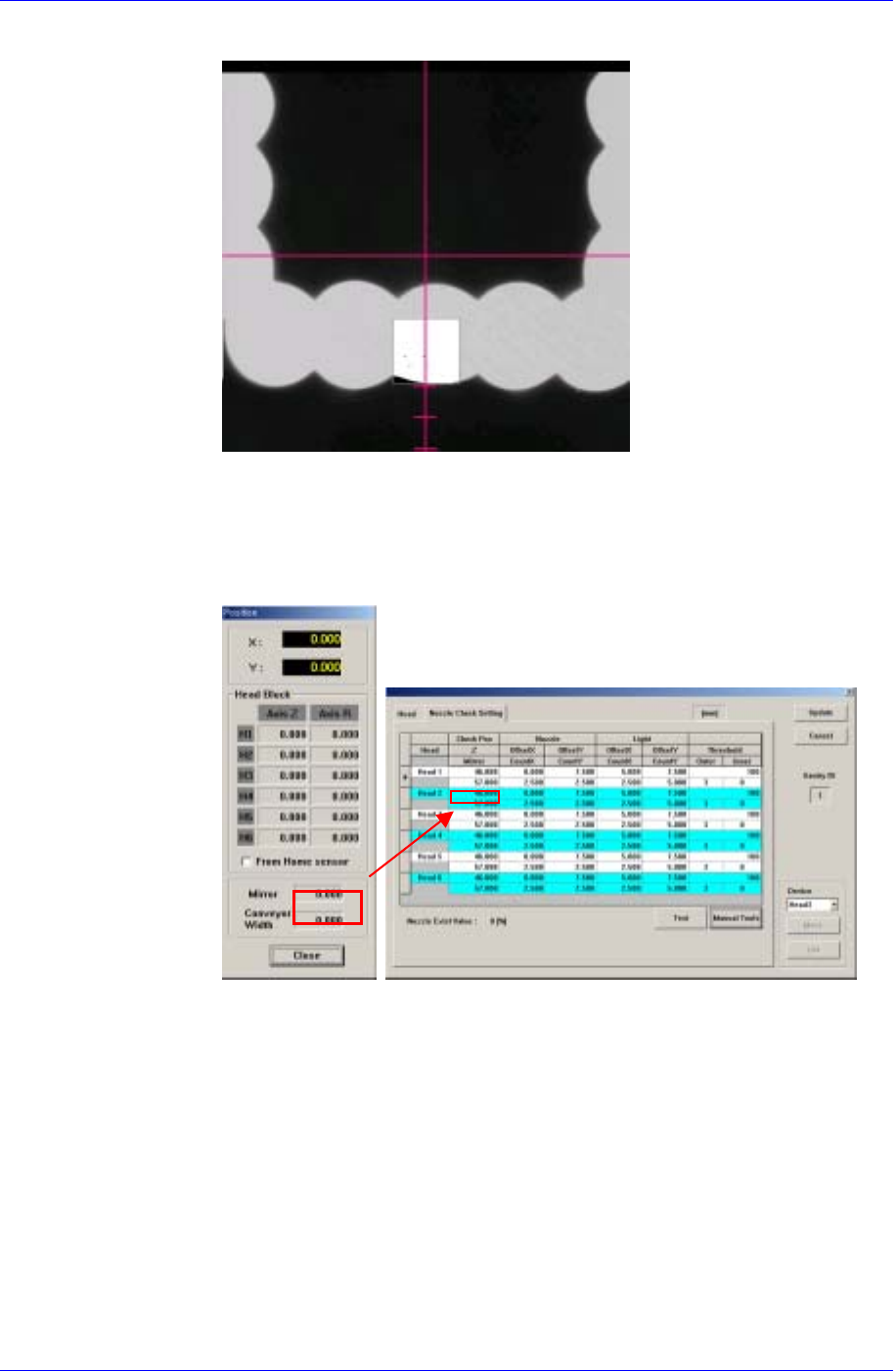
5. Move the Z-axis so that the nozzle wing surface contacts the bottom of the
outer lighting device.
15-10
Machine Calibration
15-11
Outer Lighting Device
Bottom
Nozzle wing
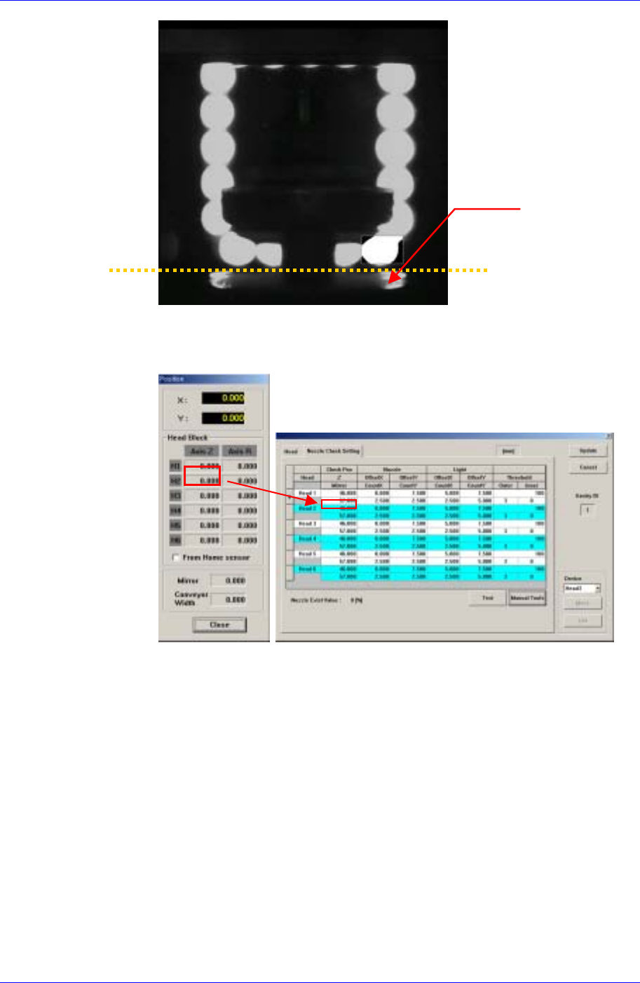
6. Close the Manual Tools dialog box.
7. At this time, apply the Axis Z value in the “Position” dialog box as the Z
value of the Check Position.
Nozzle Offset Teaching
1. If the Offset X and Y cells are clicked, the <Test> button is activated. At this
time click the <Test> button.
2. The test area is displayed as a box on the vision screen. Set the Offset X and
Offset Y values so that the test box is placed at the center of the lower LED.
The coordinate system for setting X and Y values is the Right-Down
coordinate system.