Administrator’s Guide(CP45FV) Eng.pdf - 第53页
V iew Menu 4-3 <Get> button Gets the coordinates of the current motor -ax is and displays it in the <Position> group. <Home> button Moves the axis to the Home position 4.1.2. Conveyor Dialog Box Ope…

Samsung Component Placer CP45FV Series Administrator’s Guide
Select the axis to move. Available axes are as follows.
XY: Selects XY axis.
Z: Selects the Z axis of the head.
R: Selects the R axis of the head.
Mirror: Selects the mirror axis of the fly camera.
Width: Selects the axis of the conveyor width.
<Head Device> combo box
To move to the axis selected in the <Axis> combo box or to get the coordinates,
select the corresponding device. Available devices are as follows.
Move Cam: Selects Teaching Camera.
Head1: Selects Head1.
Head2: Selects Head2.
Head3: Selects Head3.
Head4: Selects Head 4.
Head5: Selects Head5.
Head6: Selects Head6.
<Speed Level> group
Select the speed level while driving motor-axis.
Available speed levels are as follows.
1: Selects the fastest level of speed. (Fastest)
2: Selects the fast level of speed. (Fast)
3: Selects the middle level of speed. (Middle)
4: Selects the slow level of speed. (Slow)
5: Selects the slowest level of speed. (Slowest)
<Position> group
To move the axis or to get the coordinates of the current motor-axis, display the
position value. The displayed position value differs according to the axis selected in
<Axis>.
The position values are as follows.
X: The position value of X axis.
Y: The position value of Y axis.
<Origin> combo box
To move or to get the coordinates of the current motor-axis, select the origin.
Available origins are as follows.
Machine Logical: Selects the origin of the machine as the origin.
FeederBase Front (1): Selects the origin of the front feeder base as the origin.
FeederBase Rear (2): Selects the origin of the rear feeder base as the origin.
<Message>
Displays the information generated during the manipulation of axis.
<Move> button
Moves the axis to the value specified in the <Position> group.
4-2
View Menu
4-3
<Get> button
Gets the coordinates of the current motor-axis and displays it in the <Position> group.
<Home> button
Moves the axis to the Home position
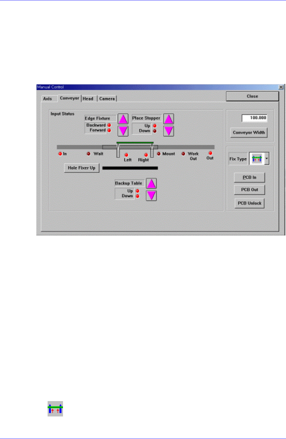
4.1.2. Conveyor Dialog Box
Operates the conveyor and the devices attached to the conveyor.
Figure 4-3. “Manual Tools – Conveyor” dialog box
<Edge Fixture> button
Moves backward or forward the edge fixer.
<Place Stopper> button
Moves up or down the place stopper.
<Backup Table> button
Moves up or down the backup table.
<Hole Fixer Up> button
Moves up the hole fixer.
<Conveyor Width> edit box
Enter the conveyor width.
<Conveyor Width> button
Automatically adjusts the conveyor width to the value entered in the <Conveyor
Width> edit box.
<Fix Type> combo box
Select the PCB arrangement method.
Hole Fixer: A method of arrangement by inserting pins in the holes of the
PCB.
Samsung Component Placer CP45FV Series Administrator’s Guide
Edge Fixer: A method of arrangement by pushing the PCB from the side with
a device attached to the conveyor.
Edge Fixer2: It is the same as the “Edge Fixer” method, but it is a method of
arrangement by pushing twice from the side.
<PCB In> button
Loads the PCB in the work area. Before executing this function, the PCB
arrangement method must be set in <Fix Type>.
<PCB Unlock> button
Releases the PCB fixed in the work area.
<PCB Out> button
Releases the PCB in the operation area to the next machine.
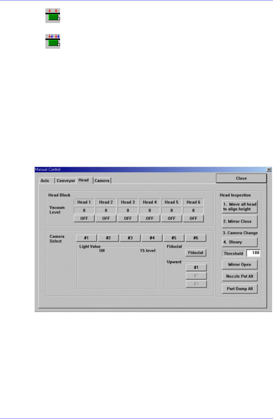
4.1.3. Head block Dialog Box
Used to turn on/off the air pressure of each head, set the light value of each camera,
open/close the mirror of the head block, and put all nozzles.
Figure 4-4. “Manual Tools – Head block” dialog box
<Vacuum level> group
Turns on/off the air pressure of each head.
<Camera Select> group
Sets the light value of the fiducial camera, fly camera, and upward camera.
<Head Inspection> group
<Move all head to align height> button
Moves the Z axis of the head to the Align height to test the head.
<Mirror Close> button
4-4