Administrator’s Guide(CP45FV) Eng.pdf - 第238页
在线预览 Administrator’s Guide(CP45FV) Eng.pdf PDF 文档。

Calibration & Setup
Machine Calibration
Chapter 15. Machine Calibration
15-1
15.1. Head [F2]
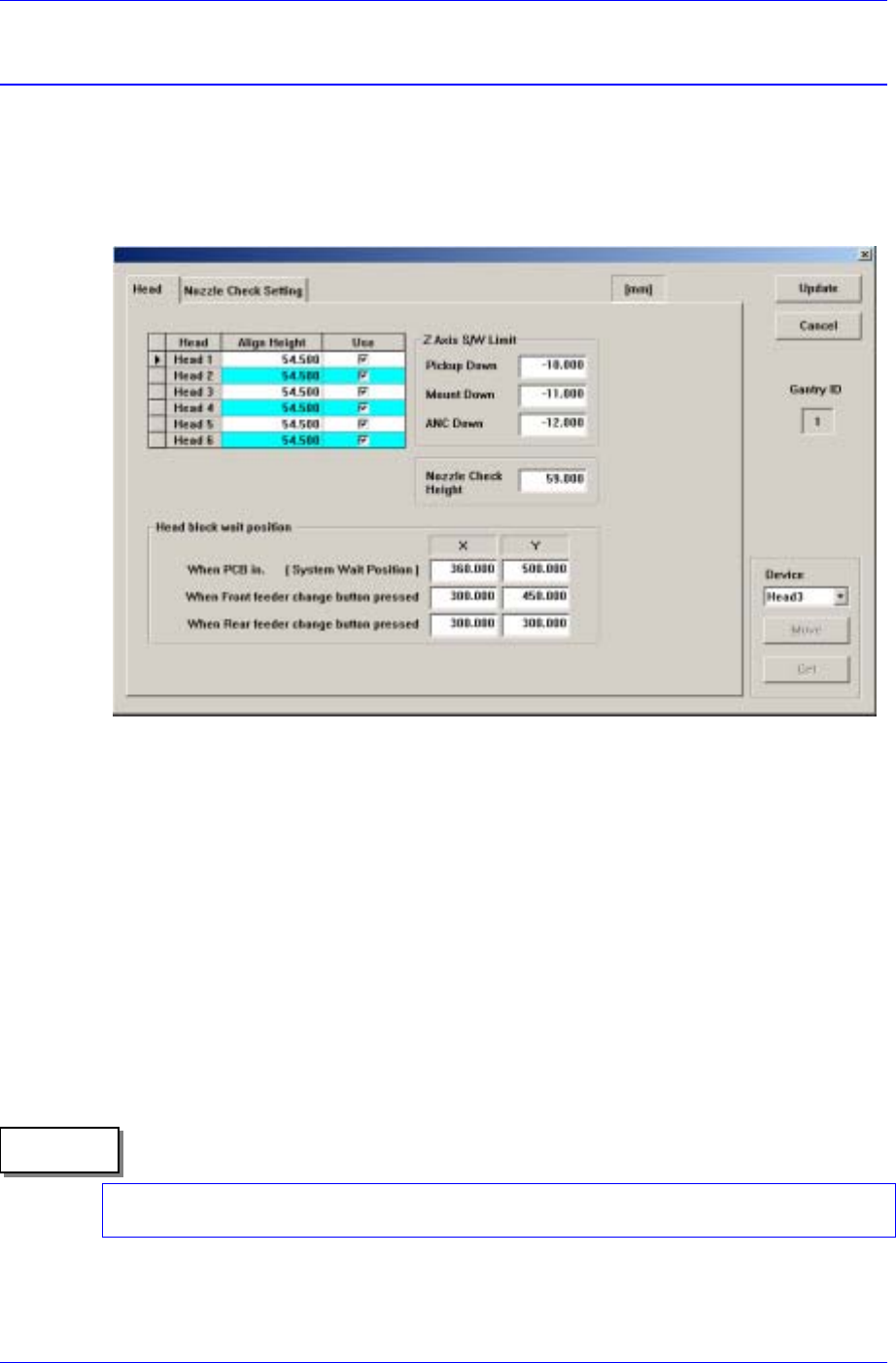
15.1.1. Head Tab dialog box
The <Head> command displays and sets the status of the head assembly. When this
button is clicked on, the following dialog box is displayed.
Figure 15-1. “Sys. Setup : Gantry / Head Information” dialog box
<Gantry ID> Static box
Displays the ID of the gantry to which the head assembly is attached.
<Grid> group
Set the data on the head.
<Head No> column
Displays the head number.
<Align Height> column
Set the align height.
The value “54.5” refers to the default value applied to this machine, which means
the position where the component is aligned on the top surface of the PCB.
Memo
When changing the data, the head may operate in the wrong direction since the
component alignment position is changed.
<Use> column