Administrator’s Guide(CP45FV) Eng.pdf - 第156页
Samsung Component Placer CP45FV Series Administrator ’ s Guide Position Y : Displays the Y position of the current placement point. <Adjust> check box Displayed only when the fiducial mark has been set. To …
Step Programming
9-3
For example, if the number of current placement points is 10 and the number of array
PCB is 4, then the total number of placement points is expanded to 40.
If it is already expanded, returns to the original status. At this time, all placement data
disappear except for no. 1 array PCB.
<Move> group
Moves the head assembly by rotating the shaft of the X and Y driving motors to the
placement point of the previous or following row of the current row.
<Move Prev>
button
Moves the head assembly by rotating the shaft of the X and Y driving motors to
the placement point of the previous row of the current row.
<Move Next>
button
Moves the head assembly by rotating the shaft of the X and Y driving motors to
the placement point of the following row of the current row.
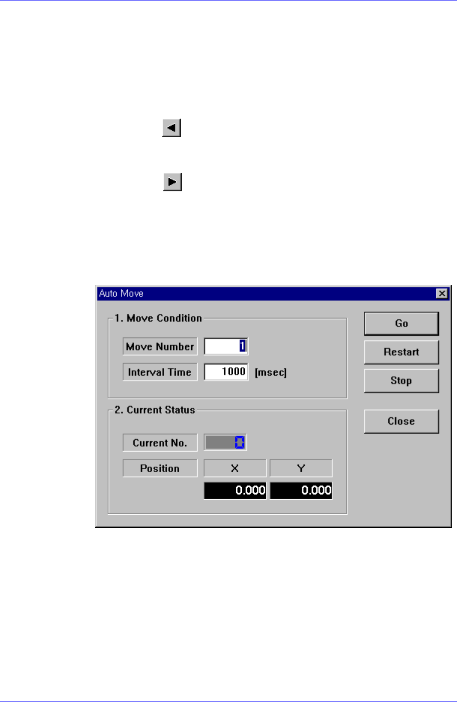
<Auto> check box
To move continuously, check this check box. When this check box has been
clicked on and <Move Prev> or <Move Next> is clicked on, the following dialog
box is displayed.
<1. Move Condition> group
Set the number of placement points to move and the time interval between
movement.
Move Number: Set the number of placement points to move continuously.
Interval Time: Set the time interval between placement point movements.
<2. Current Status> group
Displays the number and position of the current placement point.
Current No.: Displays the current placement point number.
Position X: Displays the X position of the current placement point.
Samsung Component Placer CP45FV Series Administrator’s Guide
Position Y: Displays the Y position of the current placement point.
<Adjust> check box
Displayed only when the fiducial mark has been set.
To move after adjusting by using the fiducial mark of the PCB, check this check
box.
<Find> group
Edit box
Set the string of characters to find. At this time, the column in the grid containing
the string of characters must be specified first.
<Find Prev>
button
Finds the string of characters set in the edit box in the previous lines of the
current line of the column specified in the grid.
<Find Next>
button
Finds the string of characters set in the edit box in the next lines of the current
line of the column specified in the grid.
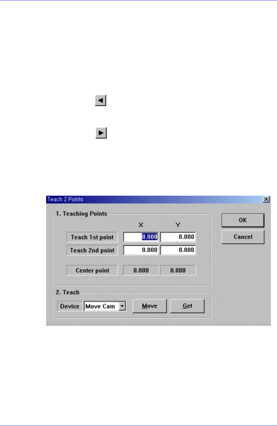
<2Pt. Teach> button
When a placement position is set, performs the function of teaching 2 corner points,
calculating the center point and using it as the placement point. When this button is
clicked on, the following dialog box is displayed.
Figure 9-2. “Step: Teach 2 Points” dialog box
<1. Teaching Points> group
Set the positions of two corner points to obtain the center point.
Teach 1st point: Set the position of the first point.
Teach 2nd point: Set the position of the second point.
Center point: Displays the center point by using the positions of two corner
points.
<2. Teach> group
Used to move the head assembly or spindle to the set position by rotating the
9-4

Step Programming
9-5
shafts of the X, Y-axes driving motors or to obtain the current shaft locations of
the X, Y-axes driving motors.
<Device> combo box
Used to select the corresponding device when moving the head assembly by
rotating the shafts of the X, Y-axes driving motors or to obtain the current
coordinate of the device to be selected. Available devices are as follows;
Move Cam: Selects Teaching Camera.
Head1: Selects Head1.
Head2: Selects Head2.
Head3: Selects Head3.
Head4: Selects Head4.
Head5: Selects Head5.
Head6: Selects Head6.
Beam: Selects Beam.
<Move> button
Moves the head assembly by rotating the shafts of the X, Y-axes driving motors
using the device selected from the <Device> combo box. Before executing
“Move”, the edit box corresponding to the desired position must be clicked on
with a mouse.
<Get> button
Reads in the current position of the XY axis of the device selected in <Device>.
Before executing “Get”, the edit box corresponding to the desired position must
be clicked on with a mouse.
<OK> button
Sets the obtained center point as the new pickups point and closes the dialog box.
<Cancel> button
Ignores the obtained center point and closes the dialog box.
<Fiducial…> button
If the placement point has a fiducial mark, sets the fiducial mark data. When this
button is clicked on, the following dialog box is displayed.