Administrator’s Guide(CP45FV) Eng.pdf - 第93页
Part Registration 7-9 7.2. CHIP component dat a setting 7.2.1. CHIP-Circle component data setting Set the align data for circular CHIP components. Figur e 7-7. “ Align T ype = V ision,, Package Gr oup = CHIP-Cir cle ” di…
Samsung Component Placer CP45FV Series Administrator’s Guide
Displays the component data list of the data selected in <Align Type> and
<Part Group>.
<Update Part> button
After adding a New Part, use it to add the New part to the Local DB.
<Change Group> button
Changes the group of the selected part from current part group to another group.
<Library Delete> button
Deletes the component data selected in <Part List> from the Local Part DB.
<Copy to PCB Part>
button
Copies the component data selected in <Part List> of <2. Library> group to <1. PCB
Part List> group.
<Copy to Local Part DB>
button
Copies the component data selected in the <1. PCB Part List> group to the Local Part
DB.
<Copy All to Local Part DB>
button
Copies all component data in the <PCB Part List> group to the Local Part DB.
<Cancel> button
Cancels all edited data.
Caution
If you move to another screen while editing the “Part”
dialog box, the edited data is saved automatically.
7-8
Part Registration
7-9
7.2. CHIP component data setting
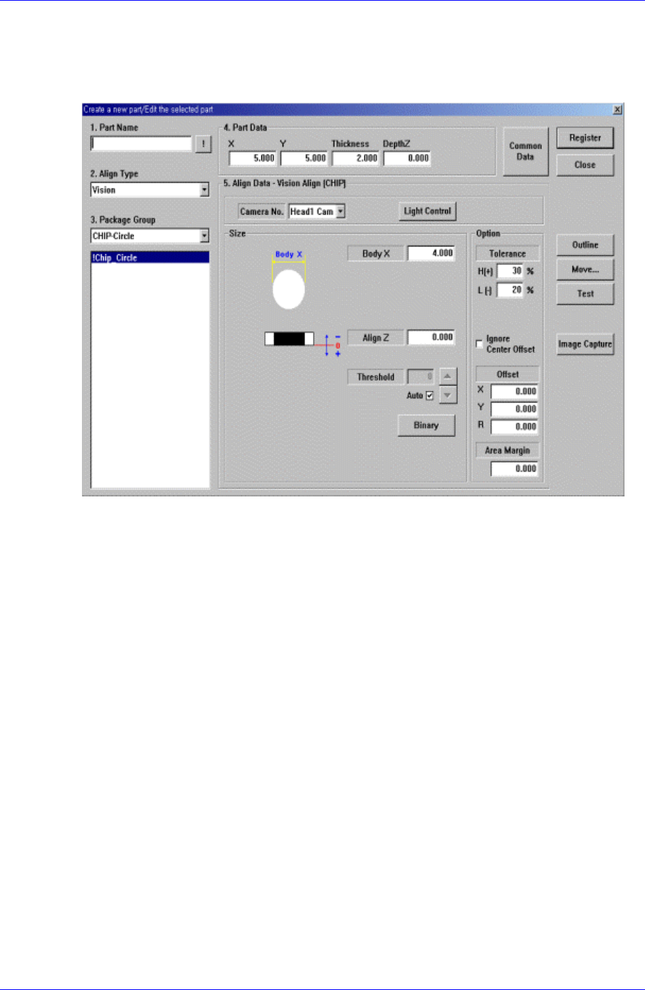
7.2.1. CHIP-Circle component data setting
Set the align data for circular CHIP components.
Figure 7-7. “Align Type = Vision,, Package Group = CHIP-Circle” dialog box
<Size> group
Set the align size.
<Body X> edit box
Set the diameter of component.
<Outline> button
Displays the outline of the component on the vision monitor by using the set align
data.
<Repeat…> button
Performs the component recognition test repeatedly. It is not explained here since it is
for debugging.
<Close> button
Ignores the set data and closes the dialog box.
7.2.1.1. Common Align Data
The following items are common to CHIP component.
<Camera No.> combo box
Select the camera to recognize the component. Available cameras are as follows.
Fix1 Cam: Fix Camera1. (If Fix Camera1 is installed)
Fix2 Cam: Fix Camera2. (If Fix Camera2 is installed)
Samsung Component Placer CP45FV Series Administrator’s Guide
Fix3 Cam: Fix Camera3. (If Fix Camera3 is installed)
Head1 Cam: Fly Camera for Head1.
Head2 Cam: Fly Camera for Head2.
Head3 Cam: Fly Camera for Head3.
Head4 Cam: Fly Camera for Head4.
Head5 Cam: Fly Camera for Head5.
Head6 Cam: Fly Camera for Head6.
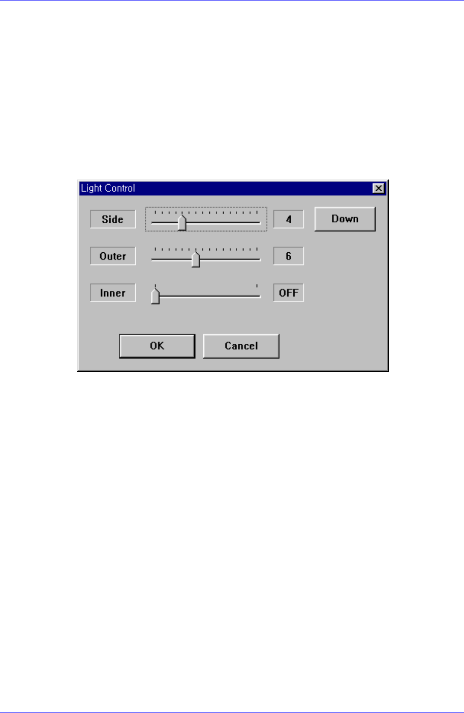
<Light Control> button
Sets the lighting for the camera to recognize the component. When this button is
clicked on, the following dialog box is displayed.
Figure 7-8 “Camera No. = Head Camera “ dialog box
<Side>
Set a value for the side light. (0 – 15)
<Down> button
Moves down the side light.
<Outer>
Set a value for the outer light. (0 - 15)
<Inner>
Set a value for the inner light. (ON, OFF)
<OK> button
Saves the set light value and closes the dialog box.
<Cancel> button
Closes the dialog box without saving the set light value.
7-10