Administrator’s Guide(CP45FV) Eng.pdf - 第271页
System Setup 16-5 16.2. Offset [F4] Sets the offset value between the devices of the head block. When this button is clicked on, the following dialog box is displayed. Figur e 16-4. “ Sys. Setup : Head Device Offset ” di…

Samsung Component Placer CP45FV Administrator’ Guide
Caution
Take a precaution since the XY axis moves.
<Offset> group
Set the offset value for the selected axis.
<Home Offset> edit box
Set the offset value when the motor of the selected axis finds Home.
<Device> combo box
Selects the corresponding device to move the head assembly by rotating the driving
shafts of the X, Y and Z-axes motors, move or rotate the spindle or obtain the current
coordinate of the device to be selected. Available devices are as follows;
Move Cam: Selects Teaching Camera.
Head1: Selects Head1.
Head2: Selects Head2.
Head3: Selects Head3.
Head4: Selects Head4.
Head5: Selects Head5.
Head6: Selects Head6.
Beam: Selects Beam.
<Move> button
Moves the head assembly by rotating the shafts of the X, Y and Z-axes driving
motors using the device selected from the <Device> combo box. At this time, the edit
box corresponding to the position to move to must be clicked on with a mouse.
<Get> button
Reads in the current positions of the XY, and Z axes of the device selected in
<Device>. At this time, the edit box corresponding to the position to be read should
be clicked on with a mouse.
<Update> button
Transmits the set data to the machine and closes the dialog box.
<Cancel> button
Ignores the set data and closes the dialog box.
16-4
System Setup
16-5
16.2. Offset [F4]
Sets the offset value between the devices of the head block.
When this button is clicked on, the following dialog box is displayed.
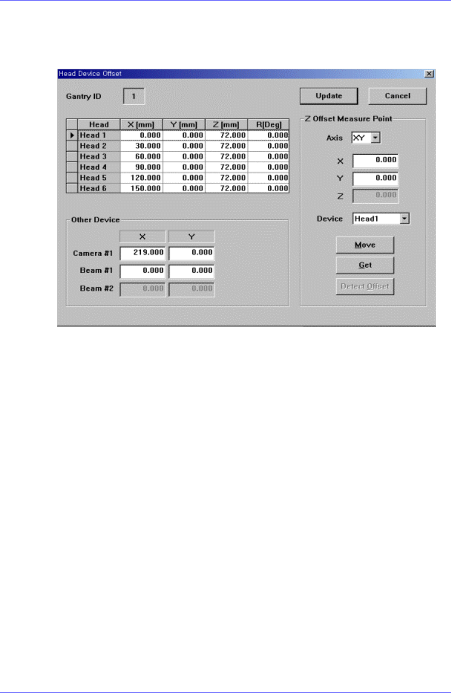
Figure 16-4. “Sys. Setup : Head Device Offset” dialog box
<Gantry ID Select> Static box
Displays the ID of the gantry to which the head assembly is attached.
<Grid> group
Set the offset value between the heads. The head offset information displayed here,
with the exception of that for the Z and R axes is updated automatically if the head
offset calibration is executed during camera calibration and the result value is
reflected.
<Head> column
Displays the head number.
<X> column
Set the X offset value. Consider the X position of head1 when the XY axis is
Home as 0 and set the offset value based on this value.
<Y> column
Set the Y offset value. Consider the Y position of head1 when the XY axis is
Home as 0, and set the offset value based on this value.
<Z> column
Set the Z offset value. The base of offset value is the top of PCB when the PCB
board is loaded.
The Z-axis offset setup procedure is as follows;
1. Select the “Current Position” in the View menu and execute the dialog box.
2. Click the <Pick> button of the ANC dialog box and mount the nozzle on the
Head1.
Samsung Component Placer CP45FV Administrator’ Guide
3. Move the head to the position above the top surface of the conveyor cover
using the teaching box.
4. Move the Z-axis slowly using the teaching box so that the nozzle tip touches
the top surface of the conveyor cover.
5. Check if the Z-axis value of Head1 is 6mm in the Current Position dialog
box. The conveyor cover top surface is designed so that the Z-axis height
becomes 6mm with the PCB top surface being the reference.
6. If it is not 6mm, correct the Z-axis value of Head1 of the Head Device Offset
dialog box as much as the offset value, move the Z-axis down again so that
the nozzle tip touches the top surface of the conveyor cover, and check if the
Z-axis value of Head1 is 6mm in the Current Position dialog box.
7. If there is no problem, enter the Z-axis value of Head1 in the Head1 Z
column in the Current Position dialog box directly.
8. Perform calibration for the heads from Head2 to Head6 in the same manner.
9. When the above procedure is completed, click the <Update> button to apply
the changed value.
<R> column
Sets the R offset value. It performs calibraton to mount the directional nozzle
accurately.
The Theta(R)-axis offset setup procedure is as follows;
1. Select the “Current Position” in the View menu and execute the dialog box.
2. If the head has a nozzle, click the <Put> button of the ANC dialog box to
place the nozzle on the pocket.
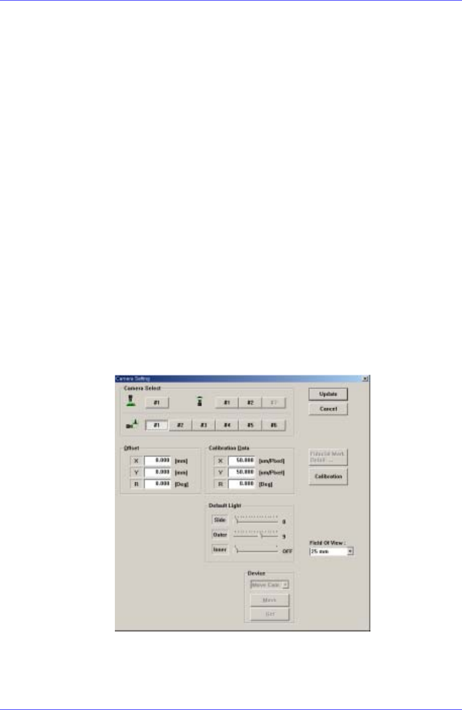
3. Select the Fly Camera 1 in the following Camera Setting dialog box.
4. Close the mirror using the teaching box.
5. Using the teaching box, rotate the Theta-axis so that the shape of the nozzle
holder becomes “C” shape while watching the vision monitor.
6. Then enter the R-axis value of Head1 of the Current Position dialog box in
16-6