Administrator’s Guide(CP45FV) Eng.pdf - 第268页
Samsung Component Placer CP45FV Administrator ’ Guide 16.1. Limit [F3] The <Limit> comm and sets the limit position of each axis to move. When this button is clicked on, the following dialog box is displayed. Figur…
System Setup
Chapter 16. System Setup
16-1
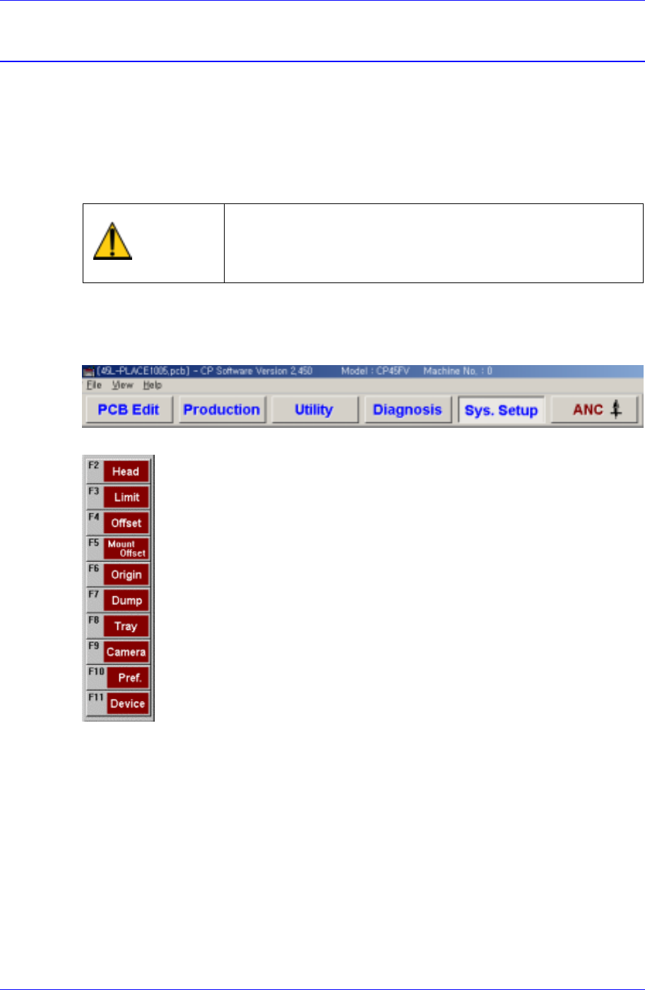
The Sys. Setup menu is composed of ten submenus: Head, Limit, Offset, Mount Offset,
Origin, Dump, Tray, Camera, Pref., and Device.
Items in this menu are set prior to the delivery of the machine. Therefore, do not
perform Calibration (System Setup) except when reset is needed due to the
maintenance of the machine.
Warning
Changing the set up status by an unauthorized user could
damage the machine or result in personal injury.
Unauthorized user must not change the set up status of
the machine.
When a submenu of the <Sys. Setup> menu is selected, corresponding dialog box is
displayed on the screen. While the corresponding dialog box is displayed, selecting the
menu once more activates the dialog box.
Figure 16-1. When the Sys. Setup Command is Selected
Figure 16-2. Submenus of the Sys. Setup command
Samsung Component Placer CP45FV Administrator’ Guide
16.1. Limit [F3]
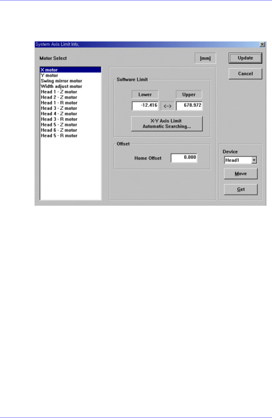
The <Limit> command sets the limit position of each axis to move.
When this button is clicked on, the following dialog box is displayed.
Figure 16-3. “Sys. Setup : System Axis Limit Info.” dialog box
<Motor Select> group
Select the motor axis for which to set the limit. Available axes are as follows.
X motor: X axis of XY Frame
Y motor: Y axis of XY Frame
Swing mirror motor: Mirror axis of the head block.
Width adjust motor: Width motor axis of conveyor.
Head1 – Z motor: Z axis of Head1
Head2 – Z motor: Z axis of Head2
Head1 – R motor: R axis of Head1
Head3 – Z motor: Z axis of Head3
Head4 – Z motor: Z axis of Head4
Head3 – R motor: R axis of Head3
Head5 – Z motor: Z axis of Head5
Head6 – Z motor: Z axis of Head6
Head5 – R motor: R axis of Head5
The swing mirror motor setup procedure is as follows;
1. Select “Current Position” in the View menu and execute the dialog box.
2. Execute the homing of the machine using the teaching box.
16-2
System Setup
16-3
3. Move the head to the middle area of the Front Feeder Station using the teaching
box.
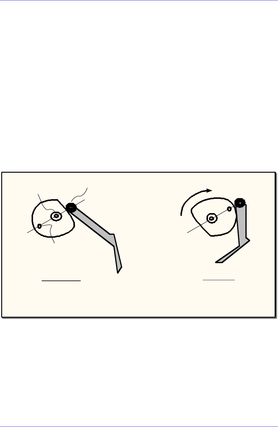
4. Using the teaching box, align the Idler wheel, CAM driving axis and Mark so that
they are aligned on a straight line. The position at this time should be 180 degrees
(refer to the following figure).
When performing a visual check, care shall be taken to avoid safety related
accidents. And, the user must operate the machine directly.
5. Check if the centers of the three circles are aligned on the straight line using a
general scale ruler.
6. Check the Mirror Data indicated in the Current Position dialog box, measure the
following offset value, and enter it.
Example 1: If the indicated data is 185 degrees, enter 5.00 in the Home Offset.
Example 2: If the indicated data is 175 degrees, enter -5.00 in the Home Offset.
7. After completing the setup, click the <Update> button to reflect the changed
value.
8. Then if the screen asking whether to home the machine is displayed, select “No
(N)”.
9. Perform homing of the machine using the teaching box.
180˚Position
Home Position
Idler wheel
Driving axis
Mark
Swing Mirror
Cam
<The simplified Cam Follower diagram of CP-45>
<Software Limit> group
Set the limit position of the selected axis.
<Lower> edit box
Set the lower limit position.
<Upper> edit box
Set the upper limit position.
<X-Y Axis Limit Automatic Searching…> button
When this button is clicked on, the limit position of the XY axis is searched
automatically.