Administrator’s Guide(CP45FV) Eng.pdf - 第85页
Part Registration Chapter 7. Part Registration 7-1 7.1. Part [F3] The <Part> command is used to register components necessary for PCB operation and edit data. The component data managed by this machine include PCB …
Part Registration
Chapter 7. Part Registration
7-1
7.1. Part [F3]
The <Part> command is used to register components necessary for PCB operation and
edit data.
The component data managed by this machine include PCB Part, Local Part Library, and
Standard Part DB. The following is the structure of each data and the relationship
between these data.
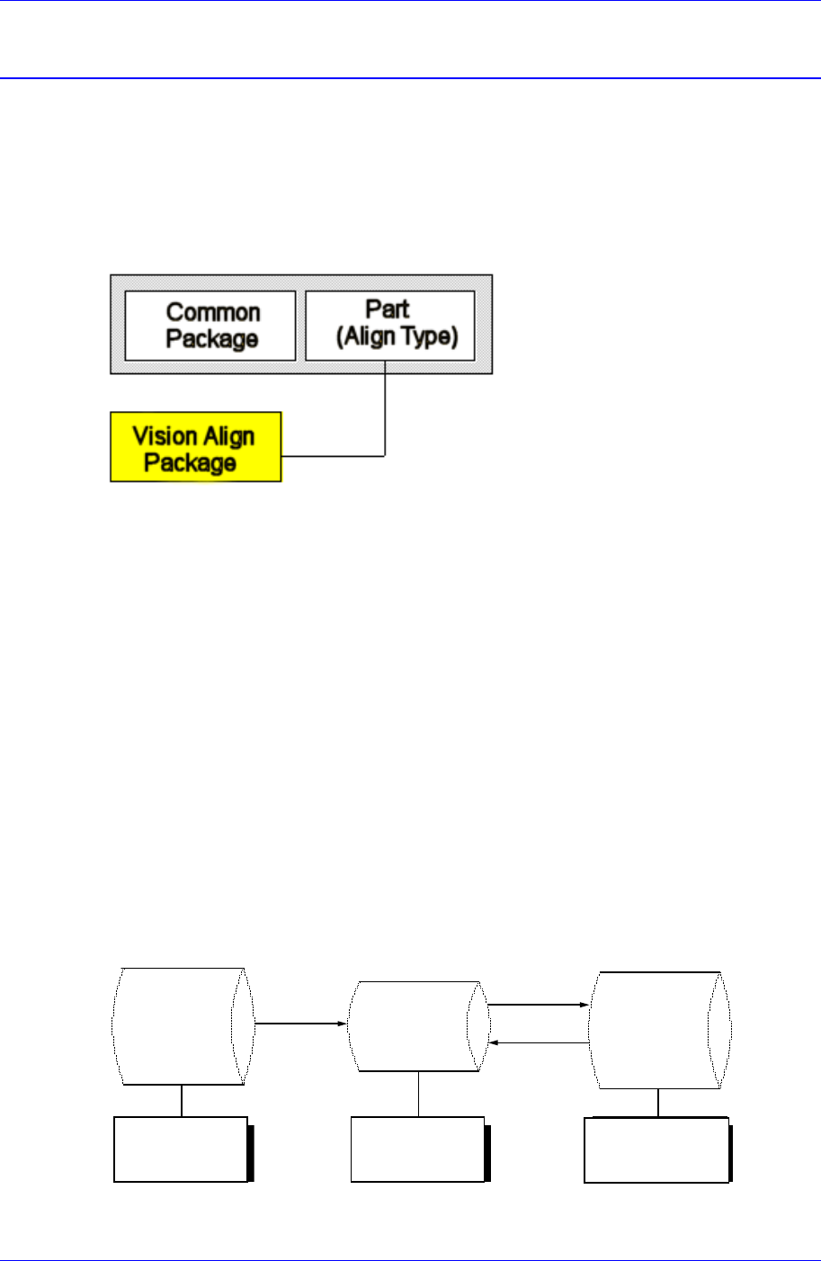
Figure 7-1. Component Data Structure
The component data in the Figure 7-1 is composed of “Part” that controls component
names and component sizes and “Common Package” that has the data related to the
machine.
The align type is setup according to the way a component shape is recognized. However,
the “Vision Align” recognizes component shape through a vision camera. The controlled
data are different depending on each align type. The vision align type is classified as
“Vision Align Package”. Set the align data to be applied now in the Align Type of “Part”.
In the Figure. 7-1, “Vision Align Package” is being set with the current align data.
Each PCB controls component data on all components operated on the corresponding
PCB and saves the component data in the Local Part DB of the machine. To create
component data for a new PCB, component data stored in the Local Part DB can be
copied. To create component data for a new component whose data is not stored in the
Local Part DB, data for a similar component stored in the Local Part DB can be copied
and edited or standard component data can be copied from the Standard Part DB and
edited. The Standard Part DB is a DB of generally used components developed and
supplied by this machine manufacturer. The relationship between component data is
shown in the following.
Standard
Part DB
PCB Part
Local
Part DB
Create
New
p
ar
t
Save
Copy
Applied to
all PCBs
Controlled by
each PCB
Controlled by
each machine
Figure 7-2. . Relationship between component DBs
Samsung Component Placer CP45FV Series Administrator’s Guide
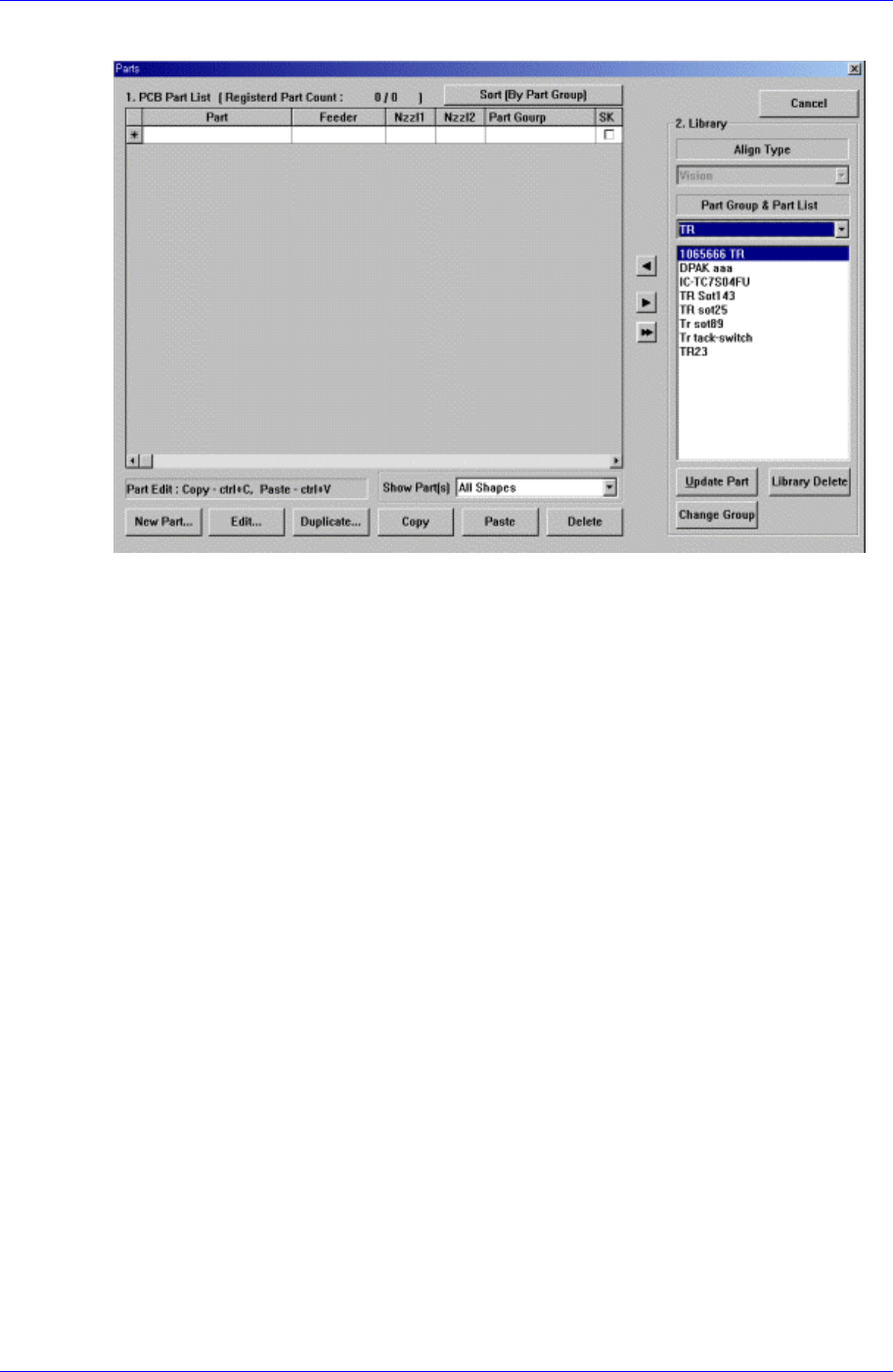
When the <Part> command is selected, the initial screen is as follows.
Figure 7-3. “Parts” dialog box
<1. PCB Part List> group
Display a list of currently registered components.
<Part> column
Displays the component name.
<Feeder> column
Displays the type of the feeder supplying components. The types of feeders are
as follows.
8mm Tape: Supply by 8mm Tape Feeder.
12mm Tape: Supply by 12mm Tape Feeder.
16mm Tape: Supply by 16mm Tape Feeder.
24mm Tape: Supply by 24mm Tape Feeder.
32mm Tape: Supply by 32mm Tape Feeder.
44mm Tape: supply by 44mm Tape Feeder.
56mm Tape: Supply by 56mm Tape Feeder.
32mm Adhensive: Supply by 32mm Adhesive Tape Feeder.
Belt Stack Stick: Supply by Belt Stack Stick Feeder.
Vibration Multi Stick: Supply by Vibration Multi Stick Feeder.
Belt Multi Stick: Supply by Belt Multi Stick Feeder.
Single Tray: Supply by Single Tray Feeder.
FW-20F: Supply by 20-stage Tray Feeder.
FW-20S: Supply by 20-stage Tray Feeder.
FW-12M: Supply by 12-stage Tray Feeder
<Nozzle1> column
7-2